AbstractIn the domain of soft real-time application design, the gap between componentspecification models and the implementations often implies that the implementations cannot fully take advantage of the specification models. To limit this gap, this paper proposes an approach to generate a QoS monitor from the timed behavior specification. To support this approach, we rely on two different component models: one focused on formal description and the other on practical implementation. Those models are interconnected by model transformation, using a Model-Driven Engineering style. 1 INTRODUCTIONRecently, hopes that modeling could take an important role in the software engineering process have been refuelled by so-called MDE (Model-Driven Engineering) initiatives, most prominently advanced by IBM with EMF, the OMG (Object Management Group) with the MDA or by Microsoft with Software Factories. The underlying idea is to promote models to be the primary artifacts of software development, making executable code a pure derivative. According to this development paradigm, software is generated with the aid of suitable transformations from a compact description (the model) that is more easily read and maintained by humans than any other form of software specification in use today. In the soft-real time domain, the industry is interested in abstract component models to build systems. Such models improve the reusability of software modules because they provide three main features [8] for designing soft real time applications: (1) a composition model that provides operators able to compose existent libraries of components, (2) an abstraction level for defining components and connectors with only precise and yet abstract properties of the components, (3) a set of analysis tools to validate architectural descriptions. To enable an architectural analysis, the specification activity must add a time information within the component interface specification. Nevertheless, even though the real-time system community and the software engineering community use the component paradigm, the details are not necessarily the same. Consequently, although standards such as AUTOSAR [3] and sysML [14], for real-time systems, or UML 2.0 [15], for software engineering, promote the concept of component, there is not currently any component model designed to specify a real-time application by assembling components with a clear semantic and a clear mapping with a real-time framework such as Giotto [9] or Simulink [6]. Our work is motivated by the need to provide a bridge between the two communities
to take the best of the different approaches: indeed software engineering
provides standards and tools for the design of system and real time system engineering
community provides semantic and tools for analysis. Consequently, we aim
at preserving the correctness verification techniques of real-time components, while
supporting component-based software architecture. Our approach aims at applying
formal composition of specifications while supporting conventional source-codebased
Figure 1: Overview of the approach The rest of this paper is organized as follows. Section 2 provides details on the languages and metamodels used in our approach. Section 3 details the component model and the real-time framework used for the implementation layer and explains the transformation process. Section 4 describes the validation of our aproach with the monitoring of the quality of of service on a robot. Finally, Section 5 describes some related work and Section 6 concludes and discusses some future work. 2 ANALYSIS AND DESIGN MODELSeveral works in different domains converge on the use of components, ports, and connectors to describe a software architecture [12]. Our approach selects a suitable subset of UML 2.0 with a special emphasis on component-based architecture design with time-related features. Furthermore, in our approach, a specification of a system consists in defining its architecture. This architecture is an abstract system specification consisting primarily of components described in terms of their behaviors, their temporal specification, their interfaces and the component assembly. This section presents the structural concepts used to define the architecture and the formalisms used to define the behavioral and the temporal properties of components. Structural elements of the component modelThe structural part of our component model is heavily inspired from the UML 2.0 architecture diagram. Nevertheless, contrary to UML 2.0, we define an abstract model with fewer concepts to limit the complexity of the language that the architect has to manipulate and to remove all the semantic variation points existing in UML 2.0. Consequently, in our component model, a component provides services and may require some services from other components. Services can only be accessed through explicitly declared ports. A port is a binding point on a component that defines two sets of interfaces: provided and required. Our component model distinguishes two kinds of components: primitives which will contain the code, and composites which are only used as a mechanism to deal with a group of components as a whole, while potentially hiding some of the features of the subcomponents. A primitive component can be seen as a basic building block in the component assembly. Our component model does not impose any limit on the levels of composition. The model thus provides two mechanisms to define the architecture of an application: connector between ports of components, and encapsulation of a group of components into a composite. A connector associates a component’s port with a port located on another component. Two ports can be bound with each other only if the interfaces required by one port are provided by the other and vice versa. The services provided and required by the child components of a composite component are accessible through delegated ports, which are the only entry points of a composite component. A delegated port of a composite component is connected to only one child component port. The behavioral partWith the interface and method definitions, a component declares structural elements about provided and required services. the behavioral part of the component model adds information about the behavior of a component. The behavior specification defines the component’s interactions with its environment. This behavior is declared by a timed automaton [2] describing the sequences of messages that may be exchanged between the component and its environment with timed properties. A timed automaton is an automaton extended with clocks, which are a set of variables increasing uniformly with time. We only consider deterministic timed automaton. Formally a timed automaton is defined as followed : Definition 1. (Timed Automaton)
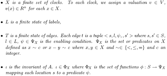
A state of an automaton is a location and a valuation of clocks who satisfies the invariant of the location. We can change of state by two types of transition: discrete transition and timed transition. The timed automaton of composite is the composition of the timed automata of the components of the assembly. This timed automaton is the expected behaviour of the assembly with respect of timed QoS. The timed properties in the timed automaton refer to QoS properties. For example, at the implementation level, if the QoS wants to have a response in a specified time, the behaviour is correct if the response arrives in time. If the response is too late, the component does not stop but the QoS is not good and the user must be inform of this violation. We will transform automatically the timed behaviour to a monitor which can check the correct execution of the components. ExampleFig. 2 illustrates the model with an example of component AudioPlayer. The AudioPlayer component provides an IAPoutsound interface that contains methods launch and sound. It is composed of 3 components: Decoder, Extraction and Source. The left side shows the structural representation of the component in UML 2.0. The right side of Fig. 2 shows an timed automaton A1 describing all possible behaviors of the Decoder1. In this automaton A1, we have two clocks: x and y. The first one is used for representing the response time of ?getSound who has to be received less than each 4 units of time. The second clock is used for modelling the execution time of the transformation of ?getSound into !sound which takes less than 2 units of time. 3 A MODEL ORIENTED APPROACH FOR CODE GENERATIONFrom the component-based software architecture representation, our approach generates a QoS monitor based on the Giotto framework [9]. This section presents the Giotto framework. We also discuss the choice of a model transformation approach to generate the code from the specification to the implementation. Finally, we provide details on the transformation of an architecture specification with time constraints to the Giotto Framework. The Giotto abstractionsGiotto is a real-time framework for embedded control systems running on possibly distributed platforms. A Giotto program explicitly specifies the exact real-time interaction of software components with the physical world. The Giotto compiler automatically generates timing code that ensures the specified behavior on a given platform. The Giotto model is based on four main concepts:
In Giotto, all communication are performed through ports. Giotto defines five kinds of ports. Two kinds of port (Sensor - Actuator) manage the input and the output interactions with the hardware layer. Two others kinds of port (Input - Output) manage the interactions with the software layer. They are used to exchange data between concurrent tasks. Finally, the private ports represent the state of a task. They are inaccessible outside the task in which they are defined.
Figure 3: Giotto meta-model In Giotto, a task has a set of inputs and outputs ports, a set of private ports and a function which infers the outputs from the input ports. This function is implemented by a sequential program and is written with a common programming language. For each function, the Giotto framework has to know the worst-case execution time of the function on each available CPU. The third type of elements in Giotto is the driver. A driver is a function that converts the value of sensor ports or outputs ports of the current mode to values for the input ports. Driver are guarded: this gard is a predicate on a sensors and output ports of a mode. The main concept of Giotto is the mode. A mode consists of a period, a set of output ports for the mode and a set of freq. A freq defines the frequency of an action during the period. This action can be an actuator update (actFreq), a task invocation ((taskFreq) or a switch to another mode (ExitFreq). A mode switch defines a transition from one mode to another mode. For this purpose, a mode switch specifies a target mode and a driver. The guard of the driver is called the exit condition, as it determines whether the switch occurs. The Giotto meta-model is presented in Fig. 3. From the specification to the implementationFrom the specification of a component, we generate the skeleton of the business component and the configuration descriptors. From the timed automata, we generate the Giotto layer implementation that controls the respect of the time constraint in the architecture of the architecture. Indeed, Giotto separates the system’s behaviour from its implementation. Then we have three levels in the implementation architecture: functional, time interaction and platform. In the functional level, we find business components generated from the specification of services and the abstract implementation. In the time interaction level, we find the Giotto layer generated from the timed automata and the time constraints. Finally, in the platform level, we find the specification of the platforms as the topology of CPUs and networks and the performance. Choosing a MDE approach has two main benefits for the QoS. The time interaction is decoupled from the functionalities. The framework improves the separation of concerns. Moreover, the generative approach improves the productivity of the development process. To define a MDE approach, we use Kermeta a model oriented language. It allows the design of the different meta-model of the generative process and the implementation of the transformation itself. Kermeta: a model oriented language Kermeta2 is an open source metamodeling language developed by the Triskell team at IRISA. It has been designed as an extension to the EMOF [16]. Kermeta extends EMOF with an action language that allows specifying semantics and behavior of meta-models. The action language is imperative and object-oriented. It is used to provide an implementation of operations defined in meta-models. A more detailed description of the language is presented in [13]. The Kermeta action language has been specifically designed to process models. It includes both Object-Oriented (OO) features and model-specific features. Kermeta includes traditional OO static typing, multiple inheritance and behavior redefinition/selection with a late binding semantics. To implement the transformation process between our component model and the Giotto, we have chosen Kermeta for four reasons. First, it gives a graphical and textual representation for designing the different meta-models identified in the process. Second, the language allows implementing a composition semantic in the component model by adding the algorithm in the body of the operations defined in the component metamodel. Third, Kermeta is suitable for model processing. It also includes specific concepts such as opposite properties (i.e. associations) and handling of object containment. In addition to this, convenient constructions of the Object Constraint Language (OCL), such as closures (e.g. each, collect, select), are also available in Kermeta. Finally, Kermeta tools are compatible with the Eclipse Modeling Framework (EMF) which allows us to use Eclipse tools to edit, store, and visualize models. This second argument is more technical than scientific, but it is very interesting to tool quickly the different meta-model defined in the approach. Generating the Giotto layer The assembly of components at the specification level gives a timed automaton describing the behaviour of the complete system. We will transform this automaton to Giotto to monitor the implementation of the components. If a component does not have a correct behaviour, Giotto can inform the user that the level of QoS is no longer correct. The real components are developed by traditionnal methods and must only inform Giotto of the arrival of messages. The first step of the transformation is to transform the timed automaton to a discrete time automaton. The discrete automaton is an automaton with discrete time. Each modification of time will be explain on the transitions. From the automaton A1, we will create the automaton A2 as illustrated in Fig. 4. The second automaton represents the states of the first automaton with discrete and time transitions. For the example, locations s0 and s1 have only discrete transitions. The two clocks are reinitialized before being used so no timed transitions are used before their initialization. Each timed transition increases the time unit by 1 so for the state wait, which must hold no more than four units of time, it is transformed to four states.
Figure 4: Transformation of automata Then the discrete automaton is transform to a simulation automaton. A simulation automaton represents what must be received within a unit of time. He is construction by finding special paths in the discrete automaton. The paths are cycle or path finishing with a timed transition. The final automaton is presented by the automaton A3 of the Fig. 5. The second step of the transformation is to produce the Giotto code. This step
Figure 5: Simulation automaton is made with the help of MDE. A model transformation helps us to create the Giotto model. A pretty printer was created for the Giotto meta-model. This generates the textual representation used as input to the Giotto compiler as illustrated in Fig. 7. The meta-model of timed automata with states is represented in figure Fig. 6. The main idea of the transformation is to create one mode for each states of the timed automata and mode switches for transitions. The code produced for the example is:
Figure 6: Meta-model of timed automata with state The time unit used for our timed automata is second wheras for Giotto it is millisecond. For example, the state s2 has 3 transitions: two discrete transitions ?getSound and ?getSound−!sound and 1 time transition. The corresponding mode s2() has 3 mode switches. The discrete transition is transformed to mode switches exitfreq 1 do s3(Cgetsound − sound) and exitfreq 1 do s3(Cgetsound) where Cgetsound − sound and Cgetsound check the arrival of messages. The timed transition is transformed to a mode switch exitfreq 1 do s2 − 2(True) which means if nothing happen during the period the automaton changes of state with a time transition. When a state can’t evolve with a time transition, the behaviour can be violated if nothing occurs during the period. The user must be informed of this violation. To achieve this, we add a mode switch to an error mode to inform the user. This case happens in the state s3 and s2 − 3 and the mode switch exitfreq 1 do error(True) is added to their corresponding modes. The addressed domain is QoS so the program will not stop if a message is not received. For the example, we introduce a single mode error. In reality, different modes will be introduced depending of the policy of QoS: allowing five kinds of error and enabling the reconfiguration of the assembly for example.
Figure 7: generated code Concrete implementation consistencyOur approach aims at removing the gap between the techniques used by the developers to implement the applications and the model used by the designer/the architect to specify and analyze their system. The use of model transformation techniques ensures that the concrete implementation has the same time constraints than the specification and the abstract implementation. At the concrete implementation level, the respect of these constraints is checked by the addition of a real time controller on the component to interact with the QoS monitor. Besides, the use of Giotto as a concrete implementation target allows the architect to check if the specification of the platform is constrained enough to obey the time constraints. The main interest of our approach consists in generating the concrete implementation time consistency checking from the specification. The Giotto real time framework guarantee the time correctness. Consequently, the implementation of the adaptation policy in the case of QoS contract violation does not tangle the functional components. For the moment, the main limitation of the approach is the risk of state explosion of the timed automata increased by the discretization of the different clocks in the transformation process. This risk is limited with the calculation of the highest discretization step for each clock.
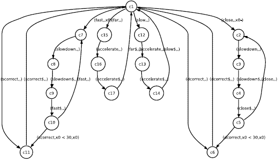
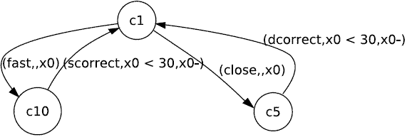
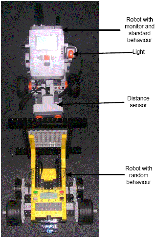
Figure 8: Behaviour of the robot
|
 |
Sébastien Saudrais is a PhD student at the Irisa at Rennes, France.His research interests are Time Quality of Service and Component Based Software Engineering. He can be reached at sebastien. saudrais@irisa.fr. |
|
 |
Olivier Barais received the engineering degree from the Ecole des Mines de Douai, France in 2002 and the PhD in computer science from the University of Lille 1, France in 2005. He is an associate professor at the University of Rennes 1, France. His research interests are Component Based Software Design, Model-Driven Engineering and Aspect Oriented Modelling. He can be reached at olivier.barais@irisa.fr. | |
 |
Laurence Duchien obtained her Ph.D degree from University Paris 6 LIP6 laboratory in 1988. She is currently full professor at the department of computer science at University of Lille, France since 2001 and she is the head of the INRIA team-project ADAM (Adaptive Distributed Applications and Middleware) http://adam.lifl.fr. Her research interests are centered on the area of componentbased architecture design, software evolution and model driven engineering. She currently involves in ERCIM Group Software Evolution and in AOSD-Europe NoE. She can be reached at laurence. duchien@lifl.fr. | |
 |
Noel Plouzeau is an associate professor of Computer Science at the Rennes 1 University. His research topics currently include software components, model-driven design processes, management of performance and quantitative aspects in component-based applications. He can be reached at noel.plouzeau@irisa.fr. |
Cite this document as follows: Sébastien Saudrais, Olivier Barais, Laurence Duchien: "From formal specifications to QoS monitors", in Journal of Object Technology, vol. 6, no. 11, Special Issue on Advances in Quality of Service Management, December 2007, pages 1–20, http://www.jot.fm/issues/issue 2007_12/article1/


