AbstractWorkflow and business process modeling approaches have become essential for designing service collaborations when developing SOA-based systems. To derive actual executable business process descriptions from the high-level workflow models, model transformation techniques can be used. Various service composition and business process languages are available for describing the executable processes. They have been developed having slightly different aims and requirements in mind. They do, however, share common key constructs, called workflow patterns that recur in descriptions given in these languages. We propose a model-driven approach for transforming workflow models given as UML activity diagrams into service composition descriptions. This paper will show how to realize a transformation from UML to BPEL and XPDL with a technology based on Triple Graph Grammars (TGGs). TGGs allow structural relationships between the different model elements to be elegantly expressed in graphical, declarative rules. We will show, in particular, how the commonly known workflow patterns recurring in the different business process languages can act as a guideline for designing the transformation rules. Based on the experiences in this application domain, we furthermore outline ways to enhance the usability and applicability of TGG for this purpose. 1 INTRODUCTIONThe development of SOA-based systems has become an actively researched application area for model-driven software development approaches. While Web service technologies, such as SOAP and WSDL, provide a way to realize SOA, they do not as such provide means to compose service interactions into more complicated business transactions. For realistic business applications, designing, specifying, and finally running such business transactions is essential. Acknowledgment of this has recently shifted the focus in Web services system development to support modeling and specifying service compositions, i.e. "programming-in-the-large". The Web service composition models and descriptions are often simply referred to as workflows. Workflows are often designed using visual modeling languages like UML[UML05] or BPMN[BPMN06], which are easy to understand and provide an abstract view to the business process to be implemented. By adding appropriate details, this kind of high-level model can be transformed into different executable business processes given in different business process languages. In this paper we propose such a model transformation approach, which currently supports transforming workflow models given as UML activity diagrams to BPEL[BPEL03] and XPDL[XPDL05] descriptions. The approach can be conveniently extended to support other business process languages as well. Different aims and requirements have driven the development of various workflow and business process languages, resulting in different structural representations. For instance, BPEL is a language focusing on service orchestration, optimized for a notation in nested XML elements, while UML activity diagrams and XPDL are graph-based process description or workflow languages. Because of the structural differences, specifying a transformation may be quite complicated. However, even though the workflow and business process languages vary a lot, they all also share certain essential key constructs that recur in concrete workflow languages. Such generally accepted workflow patterns have been cataloged in [Aalst03b]. These workflow patterns can be used not only to identify the essential, corresponding parts in the source and target models, but also as a shared understanding of the semantics of these key structures. For model transformations in general, relying on commonly known patterns with well-understood semantics provides significant aid during the whole life-cycle of the transformations, including their construction, maintenance, and comprehension. In this paper, we propose an easily extensible strategy and its practical implementation for workflow model transformations, relying on workflow patterns to correctly translate these key behaviors. We furthermore show how such transformations can be implemented using a transformation technology based on Triple Graph Grammars (TGGs)[ Schürr94 ]. There are significant benefits using TGGs for this application. First, the TGG rules allow the designer to declaratively specify bidirectional transformations. Second, since the rules are presented graphically, they are easy to comprehend and edit. We also show how the correspondences between the workflow languages on the level of workflow patterns can be conveniently expressed in TGGs, which allows an elegant transformation rule design. In this paper, we will
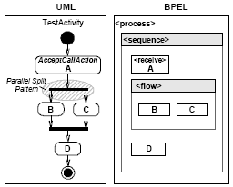
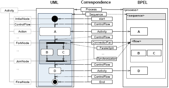
The paper is structured as follows. Section 2 introduces the background techniques and tools of our approach with an introductory example. In Section 3, the proposed transformation is discussed in detail, with an extended example shown in Section 4. We relate our transformation with other existing model-driven approaches and tools in Section 5. Finally, we conclude in Section 6 and present some future research directions. 2 BACKGROUNDIn the following, a rough structural comparison of the workflow models involved in our application is given. We also give an example of the corresponding workflow patterns occurring in these models. Furthermore, we introduce the application of Triple Graph Grammars for model transformations. Graph and Block Oriented Workflow LanguagesTo specify transformations between workflow models, their structural and semantic relationships have to be analyzed. Finding such relationships can be easy if the models are structurally similar. Workflow languages generally describe in which order tasks or activities are performed in a process. In particular, activities can be repeated, be performed optionally, occur in parallel, and be synchronized again at a certain point. To describe this, all workflow languages most fundamentally make use of activity elements (sometimes called actions ). An expression of their relative order and the above-mentioned structural composition is called the control flow of the process. Now, when transforming UML activity diagrams to BPEL descriptions, we find significant differences, especially in the representation of the control flow. In languages like UML activity diagrams (or XPDL), the control flow is explicitly represented by connecting successive actions with ControlFlow elements resulting in a graph structure. Furthermore, there are nodes specifying choices, parallel splits and joins of the control flow. Such languages are therefore called graph-oriented [Mendling05]. In the case of BPEL, the control flow is rather defined by nesting certain block elements called structured activities, which determine the execution order of the contained process elements. BPEL is thus called block-oriented [Mendling05]. A comparison of a simple UML activity diagram and an illustration of the corresponding BPEL structure are shown in Figure 1.
Figure 1. UML Activity Diagram and an illustration of the corresponding BPEL structure As shown in Figure 1, there is a direct one-to-one mapping between the AcceptCallAction A in UML and the Receive-Activity A in BPEL. The same applies to all other actions accordingly. However, the UML ControlFlow elements have no directly corresponding elements in the BPEL model1. To identify relating model elements, we have to consider larger model patterns. For example, the parallel structure of Actions B and C in UML corresponds to the Flow-block in the BPEL model. Accordingly, the overall sequence containing Action A, the aforementioned parallel structure and Action D corresponds to the Sequence-block in the BPEL model. Workflow PatternsLooking at these structures more closely, a number of workflow patterns can be identified. Such patterns have been identified by Aalst et al. [Aalst03a]. They capture common behavioral elements of business processes and concentrate on analyzing control flow aspects. The above example contains the following set of patterns (defined according to [Aalst03a]):
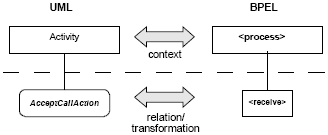
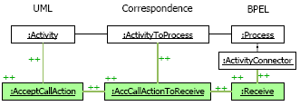
Model Transformation based on TGGsNow, to introduce the transformation mechanism, we initially consider the simple case of transforming an Action from the UML Activity to an Activity in a BPEL process. In this particular case, according to Figure 1, we choose an AcceptCallAction in UML, which specifically corresponds to a Receive -Action in BPEL. We want to express this relation in a transformation rule as abstractly shown in Figure 2.
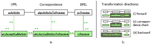
Figure 2. A simple transformation rule and its application in different transformation directions In this rule, we state that an AcceptCallAction relates to a Receive-Activity when there exists a relation between their parent elements, Activity and Process . Relations of this archetype can be expressed using Triple Graph Grammar (TGG) rules. The TGG rule corresponding to the abstract relation above is shown in Figure 3a. The model patterns are represented using a notation similar to object diagrams.
Figure 3. TGG rule example In this TGG rule, there are three columns. The outer columns contain the related domain model elements, as shown in Figure 2. They are called the domain sides of the rule. Additionally, in the middle column, there is the correspondence side where the relation that exists between these domain model elements is expressed by correspondence nodes . These correspondence nodes may connect arbitrary nodes in the domain sides. Then, in all sides of the TGG rule, there are two different types of nodes. First, there are the green nodes (shown in gray in black and white printouts), additionally labeled with "++", which represent the actual relation of model elements that shall be expressed by this rule. Furthermore, there are the white nodes, which express the context in which the relation between the green(/gray) nodes is valid. The white nodes are therefore also referred to as context nodes . Now, as shown in Figure 3b, such TGG rules can be interpreted in different ways: for forward or backward transformation, or to check two given models for a valid correspondence. In the case of a forward transformation (see Figure 3b.i), an existing source model is given. In a scenario where the example rule in Figure 3a is applied, the source model would be a UML model and the UML side of the given TGG rule would be called the source domain side. To start a transformation, an initial start context has to be provided, which typically contains the corresponding root model elements, like the Activity and Process elements in this example. Now, a rule can be applied when the context nodes of the rule can be matched to an existing context and when the source domain side of the rule can be matched inside the existing source model (see the white pattern in Figure 3b.i). Then, the remaining, non-context nodes on the target domain side and the correspondence side can be created (see the green/gray pattern in Figure 3b.i). Therefore, the green(/gray), "++"-nodes are also referred to as creatable nodes. In this way, the related model elements are transformed and a new context is created for the application of further rules. The application of TGG rules for the backward transformation direction works accordingly. In the case where two models are given, they can be checked for a valid correspondence. The correspondence nodes are created when the given models can be parsed with the domain sides of the rules. Formally, Triple Graph Grammars are an extension to Pair Grammars [Pratt71]. By structurally mapping two graph grammars, it is possible to specify how graphs of different types relate to each other. This formalism may also be extended to Multi Graph Grammars (MGGs), allowing to relate more than two graph grammars [Königs06]. The mapping of the different graph grammars is achieved by inserting a further graph grammar to specify the correspondence of single elements in the other graph grammars. Because software models can be considered as graphs, this technique can be applied to specify relations between models. In the notation introduced in Figure 3a, the domain sides as well as the correspondence part are (single) graph grammar rules. The left hand side of such a rule consists of the context nodes. The right hand side contains both the context nodes and the creatable nodes. Therefore, the TGG rules shown here are always non-deleting rules. In this paper, we want to draw special attention to the role of the correspondence side in the transformation rules. Actually, the correspondence model built up during the transformation can be seen as the integration of all the participating domain models. Section 3 explains how a systematic meta-model integration strategy aids in the specification of the transformation rules. Model transformations play a central role in model driven software development and thus, the Object Management Group (OMG) addresses model transformations with their upcoming specification for Query/Views/Transformations (QVT) [ QVT05 ]. The declarative languages specified by QVT, QVT-Relations and QVT-Core are actually quite similar to TGGs and it has been shown that these languages can be mapped to TGGs [ Greenyer06 ]. TGGs are used in the scope of two projects at the University of Paderborn, Fujaba [Fujaba06] and ComponentTools [Gepting04]. In Fujaba, TGG rules are compiled to Java code, which performs the transformation. In contrast, ComponentTools use a model transformer that rather interprets the TGG rules [Kindler 04, Kindler 06, Rohe06 ]. This TGG interpreter has lately been re-engineered and improved for the transformation of EMF ECore [EMF06] models inside Eclipse [ Greenyer06 ]. This work furthermore shows that it is possible to provide a TGG-based implementation for the declarative model transformation languages specified by QVT, QVT-Relation and QVT-Core. We chose to use this tool for the overall features of TGGs, for its usability and convenience, and because our application is based on EMF. 3 OUR APPROACH: REALIZATION OF THE WORKFLOW TRANSFORMATIONS USING TGGAfter introducing the involved workflow models and a first example of a TGG rule, this section will now furthermore elaborate the transformation strategy. Before explaining the actual TGG rule design, we will show that it is reasonable to consider the systematic integration of the involved workflow models, especially highlighting the role of workflow patterns. Transformation principles One key aspect in comparing workflow or business process languages is their support for the aforementioned workflow patterns. Aalst et al. discuss various languages in terms of their support for the patterns [Aalst03b]. We have used their analysis and classification as a guideline when designing the TGG transformation rules. This means that our transformation supports those workflow patterns supported by UML, BPEL, and XPDL. Concerning the transformation of graph-oriented and block-oriented languages, there are several strategies available [Mendling05]. Before deciding which one to choose, the structural properties of the involved models should be analyzed. There can be structured or unstructured and acyclic or cyclic process graphs. A structured graph (as defined in [Mendling05]) can be reduced to a single element by using a set of reduction rules presented in the following.
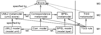
In our approach, we impose the restriction of working only with structured graphs. While structured workflow models are less expressive than arbitrary workflows, they are less prone to errors in their structure and are supported by most workflow tools. In [Eshuis06], Eshuis et al. present a strategy to compose a structured workflow starting from a set of services with data flow dependencies. It is more challenging, however, to derive a structured model from an unstructured workflow model. Existing research in this area [Kiepuszewski00] could be used to extend the presented TGG rules to support a limited set of unstructured models, but this is not further studied in this paper. In the case of BPEL, working with structured models means that we omit the usage of the graph-based links element, which allows the creation of unstructured graphs. Instead, we translate the graph-based control flows in UML or XPDL to the respective BPEL structured activity elements ( sequence, flow, etc.). Thereby, we identify the control structures instead of just mapping the control flow to BPEL links . The corresponding transformation strategy, as defined by Mendling et al. [Mendling05], is called Structure-Identification and has the advantage of creating BPEL documents that are easier to understand because the structured components are directly revealed. For the opposite direction, transforming from a block-oriented to a graph-oriented language, the nested BPEL control flow is translated to a flat process graph without a hierarchy. The advantage of this is that the behavior of the whole BPEL process is translated to one process graph, making it easy to be communicated visually. Metamodels of involved languagesOur approach is implemented in the Eclipse framework, using particularly EMF ECore models. Figure 4 shows the relationships between the UML and BPEL models. XDPL is in a corresponding role to BPEL, but is omitted from the figure for clarity.
Figure 4. Involved metamodels With the metamodels of UML, BPEL and XPDL provided, the necessary steps towards specifying the transformation consist of (a) defining the correspondence metamodel and (b) setting up the actual TGG transformation rules. Defining the correspondence modelThe correspondence nodes of the TGG rules provide the mapping between the involved domain elements. We put special emphasis on the definition of the metamodel of these correspondence elements, since it serves as a basis for creating the actual transformation rules. The correspondence metamodel should:
In order to create the correspondence metamodel, the following steps are taken in respect to the above requirements:
Figure 5 shows an illustration of the correspondences inserted between the example models from Figure 1 and the associations among these elements. According to the integration steps mentioned above, we see the Activity correspondence nodes connecting the equivalent UML Actions and BPEL Activities. Furthermore, there are the ParallelSplit and Synchronization correspondence nodes, which represent workflow patterns in both models. These nodes also mark split and join connectors in the process graph and together comprise a block that can be structurally reduced. This block is represented by a ConnectorPair correspondence node that has the ParallelSplit and Synchronization nodes as children. According to the sequence reduction rule, the whole process graph can be understood as one sequence. Therefore, a Sequence correspondence element is acting as the container of all correspondence elements representing the members of the process graph. Defining the transformation rulesThe general idea in defining the transformation rules is to create TGG rules for the following purposes:
TGG rules translating atomic Action/Activity elementsWith the definition of semantic relationships between model elements, defined in the correspondence metamodel, we already have the essential parts that have to be composed in the TGG rules. Now, the most straightforward rules are those that relate the different Action / Activity element types in UML, BPEL and XPDL, i.e. rules to transform UML AcceptCallAction, ReplyAction, CallOperationAction, etc. An example of such a rule was already shown in Section 2 (Figure 2). These rules are actually the first being applied in a transformation. Transforming the single UML Actions without considering the control flow results in a loose collection of BPEL Activities on the other side. However, these BPEL Activities have to be associated with a common context node. In the rule shown in Figure 2, it is assumed that BPEL Activities are contained in the Process element. Due to the nested block structure, however, this is not always the case. The Activities can be contained in any block element, for example a Sequence or Flow block. So, we cannot decide where to put these Activities before taking care of the control flow. Our solution to provide a common context, keeping track of these Activities and making them easily accessible from the root Process element, is an extension of the BPEL model. We insert an extra model element called ActivityConnector . It is associated with every BPEL Activity node but, through adjustments in the EMF model, remains transient when saving the BPEL models. Figure 6 shows a slightly modified version of the rule shown in section 2.
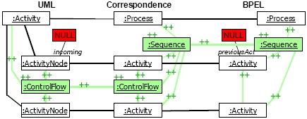
Figure 6. TGG rule example TGG rules for the Sequence workflow patternThe primary focus in the following strategy is to capture the appearing workflow patterns and the involved model elements in the TGG rules. The first pattern to be shown is the Sequence pattern. For the transformation of a sequence with n elements, we need two rules: One rule to match the beginning of a sequence and one rule to match each following element. To match the beginning of a sequence means to match an initial Action / Activity node and the one following it in the process control flow. These two nodes should be marked in some way to denote their belonging to the new-found Sequence pattern instance. Looking at the correspondence part of the "sequence_start" rule in Figure 7 already visualizes this concept.
Figure 7. The sequence_start rule Two correspondence model Activity nodes are connected by a ControlFlow and associated to a Sequence node. The ControlFlow and Sequence elements are creatable (green/grey) here, because the rule should match Activity nodes whose common Sequence and ControlFlow connection have not been translated yet. Connecting these four nodes to their corresponding nodes on the UML and BPEL sides already results in the most part of the shown "sequence_start" rule. Now, reviewing the rule in the scenario of a forward transformation from UML to BPEL, it works as follows:
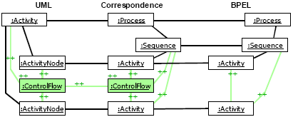
T he next Action in a sequence can be transformed with the "sequence_next" rule, shown in Figure 8. Here, the first of the two Action/Activity nodes has to be already part of a matched sequence. Therefore, in the correspondence model, this first Activity node has an already existing association to the previously created Sequence element and both this association and the Sequence element are part of the precondition of the rule. Likewise, on the BPEL side the BPEL Sequence element and the respective association are also part of the precondition. This causes the rule to append the second Activity to the existing sequence.
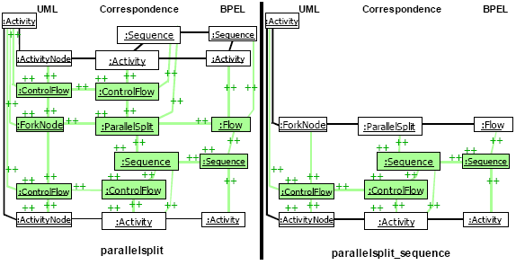
Figure 8. The sequence_next rule TGG rules for the Parallel Split patternThe next workflow pattern to be shown in its TGG rule representation is the Parallel Split pattern. The point in the process where the execution splits is mapped to a ForkNode in UML, a Flow element in BPEL, and a "route" Activity with Split type "AND" in XPDL. These elements are mapped to a ParallelSplit element in the correspondence metamodel, which also has the function to denote the pattern instance. Here, there are again two TGG rules needed: one to match the split-point, i.e. the ParallelSplit element, and another rule to match each outgoing flow of control. Because the Parallel Split pattern is usually preceded by a sequence and also the outgoing arrow of control mostly is a sequence, the presented Parallel Split TGG rules include a combination with the Sequence pattern.
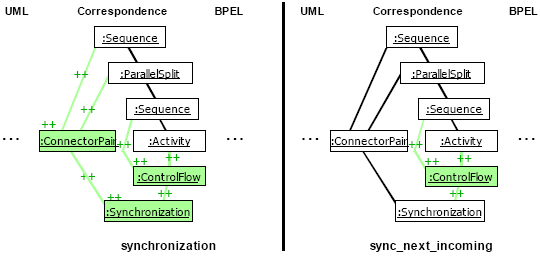
Figure 9. The two Parallel Split rules Looking at the "parallelsplit" rule on the left of Figure 9, the upper half looks similar to a "sequence_next" rule with the second Activity element replaced by the ParallelSplit element (and the corresponding UML, BPEL and XPDL side changed accordingly). Thereby, the incoming sequence, as well as the split point, is matched. In addition to that, the rule contains the nodes to match one outgoing sequence of the Parallel Split pattern. The left part of Figure 9 shows the rule to handle the other outgoing branches of control. It has the ParallelSplit element in its precondition part and matches a not yet created or matched outgoing sequence. TGG rules for other workflow patternsThe Synchronization pattern can be seen as the counterpart of the Parallel Split pattern. In our context of working with structured processes, the Parallel Split Pattern and the Synchronization Pattern both represent one part of a connector pair. This is reflected in the two TGG rules for the Synchronization pattern, as they match in the context of a preceding Parallel Split pattern instance. Thereby, the sequence preceding the ParallelSplit element is resumed after the synchronization point. All the elements in between, i.e. the parallel branches, are abstracted to the single ConnectorPair element of the correspondence model (a subclass of Activity ) and thereby reduced in a way according to the reduction rules. Figure 10 shows this concept by means of the correspondence elements of the synchronization rules.
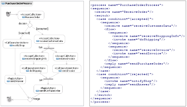
Figure 10. The correspondence part of the synchronization rules There are two rules because the Synchronization pattern involves multiple branches being brought together. The first rule detects the pattern instance and creates a new Synchronization element in the correspondence model. The second rule matches the additional incoming branches of the synchronization point. From the five basic control patterns, the remaining ones are Exclusive Choice and Simple Merge. Their implementation is mostly similar to the previous two patterns. The rest of the workflow patterns can be represented in TGG rules in a similar way. As shown before, we have already considered the integration of all three involved languages (UML activity diagrams, BPEL and XPDL) when defining the correspondence metamodel. As TGGs can be implemented for n : m transformations, and the actual implementation used also supports this, it is most convenient to add all three languages in the TGG rules. Our correspondence-model-centric way of defining the TGG rules also makes it easy to add the corresponding nodes of yet another language. One disadvantage of integrating all languages in the rules is of course that the rules quickly become rather crowded and complex. Also, the varying features of the languages might make it advisable to design a more specific correspondence model, following the principles introduced above. 4 EXAMPLE APPLICATIONTo demonstrate the applicability of the proposed approach, we now show how an example business process, depicted in Figure 11 as a UML Activity Diagram in Rational Software Architect, is transformed to a BPEL description.
Figure 11. Example business process in UML and the transformed BPEL document During the transformation, the different kinds of UML Action elements are matched by the respective single mapping rules. This happens in no particular order. The first workflow pattern to match is the sequence pattern beginning with the InitialNode element. It is matched by a variation of the above mentioned sequence_start rule, where the InitialNode element is specifically matched. The other TGG rules applied are the following:
The resulting BPEL document is shown on the right in Figure 11. 5 RELATED WORKIn recent years, many document and model transformation technologies have been developed for different application domains. There are, for example, template-based approaches, such as XSLT[XSLT99], graph grammar based approaches like GReAT[Agrawal03], VIATRA[Varro02] and TGGs, and relational approaches like MTF[MTF05] and QVT[ QVT05 ] that focus on specifying relations between model structures. The specific requirements in our application domain, however, quickly reduced the applicable model transformation approaches to just a few. Although template-based approaches are widely used, especially XSLT in web technologies, they would have resulted in an incomprehensible transformation, since the involved workflow languages are structurally complex and quite diverse. In general, we focused on declarative instead of operational transformation languages, which rather specify what should be transformed instead of how it should be done. Languages in that area include VIATRA, GReAT and MTF, for example. We also preferred transformation languages with graphical rule definitions to follow a model-driven approach and to help support the overall understanding of the transformation. The further choice among declarative languages was driven by the aim to support bidirectional transformations. There are, however, fewer languages that support both graphical rules and bidirectional transformations. The above mentioned aspects have also been acknowledged to belong to the key features and characteristics in model transformation languages, based on which these languages have been categorized [CH03, Mens06]. These characteristics include e.g. bidirectionality and support for transformation reuse, both of which are supported in our model transformation technique, namely, TGGs. It is further exogenous, since it is based on metamodels of the source and target languages. With the graphical and editable representation of the transformation rules, we also feel it is easy to use. Concentrating on graph grammar based or relational approaches that use such a graphical concrete syntax (e.g. GReAT, TGGs), languages with (partial) conformance to QVT or with compatible notations (as TGGs) came into focus. QVT (Query/Views/Transformations) is an upcoming standard for model transformations in MDA, issued by the OMG, which has recently raised a lot of attention. QVT is the result of selecting and merging previous model transformation approaches and now actually contains different, both operational and declarative, transformation languages. The declarative languages form two layers of abstraction and, for the more abstract and user friendly QVT-Relations, there is also a graphical syntax specified. However, implementations of the QVT standard are still under development and there is only partial conformance yet [SmartQVT06, ModelMorf06, Together06]. The primary reason to choose TGGs over QVT is the possibility to map the relating model patterns with a specific correspondence model. As introduced in this paper, this allows an elegant design of the transformation rules. In QVT rules, it is not possible to flexibly specify a mapping structure between the involved models patterns and thus, to the best of our knowledge, this extensible transformation strategy presented here cannot be realized in QVT. Similar to our work, other model-driven approaches have been proposed for transforming workflow models to business process description [Kalnins06, Baresi06, ETTK06, Kalnins04]. IBM's ETTK toolkit [ETTK06] also transforms the workflow models to code, namely, XML in this context. ETTK generates BPEL and WSDL documents from workflow models given in UML. Our approach currently supports both BPEL and XPDL and can conveniently be extended to support other business process languages as well. In ETTK, the transformation is made automatically and hard-coded inside the tool. It is thus neither visible to nor modifiable by the users. In the approach proposed by Skogan et al. [Skogan04], Web service compositions are designed using UML and then transformed into two variants of Web service composition languages, namely, BPEL and WorkSCo[Rito-Silva03]. While this approach focuses solely on Web service compositions, our approach can be used to generate other workflow descriptions as well. Moreover, the transformation approach UMT [Grønmo05] used in [Skogan04] is based on XSLT transformations. Finally, unlike IBM's ETTK and the approach proposed by Skogan et al., our model transformation is bidirectional. Similar to our work, Kalnins et al. proposed a transformation approach [Kalnins04] from UML Activity Diagram to any vendor specific execution language, but via another graph-based transformation language called MOLA. Compared with TGG, MOLA additionally combines the traditional structured programming in a graphical form, for example, arranging the transformation rules in sequence and invoking subprograms with parameters. With this feature, MOLA is able to scale up for complex transformations. However, MOLA does not support bidirectional transformations. 6 DISSCUSSIONFor the development and composition of services, model transformations between workflow models and process description languages are necessary. Such transformations are not trivial, because the involved languages are quite complex and often structurally diverse. However, it is possible to identify semantic relationships on the level of workflow patterns which recur in practically all these languages. Based on the observations in this domain, this paper presents a strategy to specify bidirectional model transformations by exploiting the semantic relationships of such model patterns. The transformation strategy is based on Triple Graph Grammars, which allow to reflect the detailed semantic relationships between models in graphical and comprehensible rules. As an example, we have introduced a transformation from UML Activity Diagrams to process descriptions in BPEL and XPDL. Furthermore, we have shown how this transformation can be extended to also support other workflow languages. We aim to extend this transformation to also support BPMN[BPMN06] as a workflow modeling notation. Because TGG transformations are bidirectional, they allow a reverse transformation from, for example, BPEL process descriptions back to UML Activity Diagrams. This would aid in the analysis of deployed business processes and, if combined with workflow mining tools, it could be especially useful to support understanding of executed business processes. In this application domain, TGGs have shown many advantages. Their graphical notation allows the transformation designer to specify even complex transformation patterns in a convenient way. Furthermore, the extensibility of the approach also allows to build support for new workflow languages by reusing existing transformation rules. However, the usability of TGGs could yet be improved. Potential scalability problems concerning the graphical rule notation could be addressed by enhancing the rule editor, e.g. to hide rule parts or to use concrete language syntax when available. In our application, we observed that sometimes multiple rules are needed to express the same relation between model elements, because the relation occurs in slightly different contexts. Mostly, just the nodes' type classes are different. One solution, supported by the TGG interpreter used, is to refer to a common super-class when this is possible. This was already done in the workflow-pattern related rules presented in this paper. There, the abstract UML ActivityNode superclass is used to match each of the special types of activities being part of the patterns. But, there may be cases where the involved domain models do not supply a convenient superclass structure. Then, the integration of OCL in TGGs, which is also planned for the used tool, would make it possible to cover different contexts by using if-then-else expressions. Sometimes, when the domain models become more complex, it would be convenient to have some kind of "wildcard" mechanism to cover multiple cases. However, such mechanisms would need closer investigation. In any case, the general position of the presented TGG implementation, also in its relation to existing standards and technologies like QVT and EMF, provides a good foundation for applying model transformations. The introduced strategy for the design of workflow model transformations has highlighted the benefits of using TGGs for that purpose. FOOTNOTES1 Here, we are not considering BPEL Link elements REFERENCES[Aalst03a] W.M.P. van der Aalst, A.H.M. ter Hofstede, B. Kiepuszewski, and A.P. Barros, Workflow Patterns., Distributed and Parallel Databases, 14(3), pp. 5-51, July 2003. [Aalst03b] W.M.P. van der Aalst, Patterns and XPDL: A Critical Evaluation of the XML Process Definition Language, QUT Technical report, FIT-TR-2003-06, Queensland University of Technology, Brisbane, 2003. [Agrawal03] A. Agrawal, G. Karsai and F. Shi, Graph Transformations on Domain-Specific Models, Technical report, ISIS-03-403, Vanderbilt University, 2003. [Baresi06] L. Baresi, K. Ehrig, and R. Heckel, Verification of model transformations: A case study with BPEL, Proc. of the 2nd Symposium on Trustworthy Global Computing, TGC'06, 2006. [Bézivin03] J. Bézivin, G. Dupé, F. Jouault, and J. E. Rougui, First experiments with the ATL model transformation language: Transforming XSLT into XQuery, In Proc. of the OOPSLA'03 Workshop on Generative Techniques in the Context of MDA, 2003. [BPEL03] BEA Systems, IBM Corp., Microsoft Corp., SAP AG, Siebel Systems, Business Process Execution Language for Web Services, Version 1.1. Specification, 2003. [BPMN06] Object Management Group, Business Process Modeling Notation, version 1.0, http://www.bpmn.org, 2006. [Czarnecki03] K. Czarnecki and S. Helsen, Classification of Model Transformation Approaches, In Proc. of the OOPSLA'03 Workshop on Generative Techniques in the Context of MDA, 2003. [EMF06] The Eclipse Project, The Eclipse Modeling Framework http://www.eclipse.org/emf/, 2006. [Eshuis06] R. Eshuis, P. Grefen and S. Till; Structured service composition; In Proceedings of the 4th International Conference on Business Process Management (BPM), Lecture Notes in Computer Science 4102, pp. 97-112, Springer, 2006 [ETTK06] IBM, The Emerging Technologies Toolkit (ETTK), http://www.alphaworks.ibm.com/tech/ettk, 2006. [Fujaba06] University of Paderborn, Fujaba Tool Suite, http://www.fujaba.de, 2006. [Gepting04] A. Gepting, J. Greenyer, E. Kindler, A. Maas, S. Munkelt, C. Pales, T. Pivl, O. Rohe, V. Rubin, M. Sander, A. Scholand, C. Wagner, R. Wagner: Component Tools: A vision for a tool. E. Kindler ed., Algorithmen und Werkzeuge für Petrinetze (AWPN) - Algorithms and Tools for Petri nets. Proc. of the AWPN workshop, pp. 37-42, 2004. [Greenyer06] J. Greenyer, A Study of Model Transformation Technologies: Reconciling TGGs with QVT, University of Paderborn, MSc thesis, July 2006. [Gronmo05] R. Gronmo and J. Oldevik, An empirical study of the UML Model Transformation Tool (UMT), In INTEROP-ESA, 2005. [Hornung06] T. Hornung, A. Koschmider, and J.Mendling, Integration of heterogeneous BPM Schemas: The Case of XPDL and BPEL,in CAiSE, 2006. [Kalnins04] A. Kalnins, J. Barzdins and E. Celms, Model Transformation Language MOLA, In Proc. of MDAFA, pp. 14-28, 2004. [Kalnins06] A. Kalnins and V. Vitolins, Use of UML and Model Transformations for Workflow Process Definitions, Communications of the 7th International Baltic Conference on Databases and Information Systems (Baltic DB&IS 2006)., Vilnius, Lithuania, July 3-6, pp. 3-14, 2006. [Kiepuszewski00] B. Kiepuszewski, A.H.M. ter Hofstede, and C. Bussler. On structured workflow modelling. In B. Wangler and L. Bergman, editors, Proc. CAiSE '00, Springer, pp. 431-445, 2000. [Kindler04] E. Kindler, V. Rubin, and R. Wagner, An Adaptable TGG Interpreter for In Memory Model Transformations, In Proc. of the FUJABA Days, pp. 35-38, 2004. [Kindler06] E. Kindler, V. Rubin, and R. Wagner: Component Tools: Integrating Petri nets with other formal methods. Invited talk at: 27 th International Conference on Theory and Application of Petri Nets 2006, LNCS 4024, pp. 37-56, 2006. [Königs06] A. Königs, A. Schürr: MDI - a Rule-Based Multi-Document and Tool Integration Approach Special Section on Model-based Tool Integration in Journal of Software&System Modeling, Academic Press, 2006. [MDA06] Object Management Group, Model Driven Architecture, http://www.omg.org/mda, 2006. [Mendling05] J. Mendling, K. Lassen, and U. Zdun, Transformation strategies between block-oriented and graph-oriented process modelling languages, Technical Report JM2005-10-10, WU Vienna, http://wi.wu-wien.ac.at/home/mendling/publications/TR05-Strategy.pdf, 2005. [Mens06] T. Mens, P. V. Gorp, D. Varro, G. Karsai, Applying a Model Transformation Taxonomy to Graph Transformation Technology, In Proc. Int'l Workshop on Graph and Model Transformation (GraMoT 2005), Electronic Notes in Computer Science, Vol. 152 (2005), pp. 143-159, 2006. [ModelMorf06] Tata Consultancy Services (TCS), ModelMorf, http://www.tcs-trddc.com/ModelMorf/index.htm, 2006. [MTF05] S. Demathieu, C. Griffin, and S. Sendall, Model Transformation with the IBM Model Transformation Framework, IBM, http://www-128.ibm.com/developerworks, 2005. [Pratt71] T. Pratt, Pair Grammars, Graph Languages and String-to-Graph Translations, Journal of Computer and System Sciences, volume 5, Academic Press, pp. 560-595, 1971. [QVT05] Object Management Group, MOF QVT, Final Adopted Specification, http://www.omg.org, 2005. [Rito-Silva03] A. Rito-Silva, S. Fernandes, J. Martins, and D. Domingos, Micro-workflow component framework supporting service composition, INESC-ID, Deliverable IST-2001-37724 ACE-GIS D4.2, November 2003. [Rohe06] O. Rohe, Model Transformation by Interpreting TripleGraph Grammars: Evaluation and Case Study, University of Paderborn, BSc thesis, January, 2006. [Schürr94] A. Schürr, Specification of Graph Translators with Triple Graph Grammars, In Proceedings of the 20 International Workshop on Graph-Theoretic Concepts in Computer Science, Herrsching, Germany, June 1994. Springer Verlag, 1994. [Skogan04] D. Skogan, R.Gronmo, and I. Solheim, Web Service Composition in UML, In Proc. of EDOC, pp. 47-57, 2004. [SmartQVT06] France Telecom, SmartQVT, http://smartqvt.elibel.tm.fr/, 2006. [Together06] Borland, Together Architect 2006, http://www.borland.com/us/products/ together/index.html, 2006. [UML05] Object Management Group, Unified Modeling Language Specification, version 2.0, http://www.omg.org/uml/, 2005. [Varro02] D. Varro, G. Varro and A. Pataricza, Designing the automatic transformation of visual languages, Science of Computer Programming, vol. 44(2), pp. 205-227, 2002. [XPDL05] Workflow Management Coalition, Workflow Process Definition Interface – XML Process Definition Language. Version 2.0, Document Number WFMC-TC-1025, 2005. [XSLT99] World Wide Web Consortium, XSL Transformations (XSLT) Version 1.0, http://www.w3.org/TR/xslt, 1999. About the authors
Cite this article as follows: Carsten Lohmann, Joel Greenyer, Juanjuan Jiang and Tarja Systä: "Applying Triple Graph Grammars For Pattern-Based Workflow Model Transformations", in Journal of Object Technology, Special Issue: TOOLS EUROPE 2007, October 2007, vol 6. no. 9, pp. 253-273 http://www.jot.fm/issues/issue_2007_10/paper13/ |
|||||||||||||||||||