AbstractMost graphical process models (business processes, workflows) in practice can be split into single-entry-single-exit regions either with only or-logic or with only and-logic. There is however a pattern, called the overlapped pattern, that contains or-logic mixed with and-logic in such a way, that separation is not possible. We present a method to handle arbitrary overlapped patterns and thus solve a remaining open issue with respect to the analysis of unstructured behavioral models in graphical form and their transformation to structured programs in textual form. 1 INTRODUCTIONGraphical, flowchart-like models have been used for a long time to describe behavior. Initially they helped documenting software systems, but they are more and more directly translated into runnable code. One advantage is that the source and the documentation of a software system are the same. Another advantage is that it is easier to explain a graphical behavior model to a business analyst than to do so with a program written in a traditional programming language. A third advantage is that one can zoom in and out such that more or less details become visible. There are two groups of graphical process models for workflows and business processes that are in wide use. One group contains variants of Petri-nets [1] that are, due to their mathematical abstract nature, on one hand widely used by theoretical researchers but on the other hand not appreciated by the more practical business analysts. The other group of process models can be characterized as derivatives of flowcharts. Very popular are UML Activity Diagrams [2] and BPMN [3]. A concise overview over the UML Activity Diagrams can be found in [4], the first of six introductory publications. The explicit control structure of UML Activity Diagrams and BPMN is very similar. Graphical process model editors such as the IBMWebsphere Business Modeler [5] allow the creation of models that are structurally invalid and that would therefore not run correctly. Deadlocks are examples of such structural conflicts which cause a process to wait for something it never gets. Analysis programs, either directly built into the graphical editors or available as external tools, are needed to detect structural problems, report them and support their correction. As soon as the analysis phase is over and no more errors are detected, the intended functionality is ready for deployment and the model can be transformed into runnable code. For the engine executing workflows and business processes, BPEL [6] is mostly used. Thus, an automatic and complete transformation of a graphical model into BPEL { similar to a compiler from high-level programs to machine code { is needed. This is however not easy because of the structural di erences between the representations. Process models specified in graphical form using languages such as UML Activity Diagrams or BPMN specify behavior as directed graphs where the nodes represent activities and the edges continuations. Cycles in the graph are used for repetitive tasks leading to an unstructured representation of loops because edges serve a similar purpose as the goto-statements in programming languages. The transformation to textual programming languages such as BPEL with while-loops for repetitive activities is therefore a transformation from an unstructured specification of behavior into a structured form and has strong similarities with algorithms such as the one presented in [7] that are used to eliminate goto's in code written in high-level programming languages. Several groups claim to have solved this problem, but even the most advanced method in [8] cannot translate every workflow automatically and needs a component library for manually transformed parts and their reuse. In [9], we proposed an algorithm that performs analysis and transformation of graphical process models incrementally and fully automatically, and also claimed that it is complete. A workflow is first decomposed into a tree of single-entry-single-exit regions using the approach described in [10] that is linear in time. These regions are afterwards processed independently of each other using a rule-based transformation. The rules were supposed to handle all structurally sound process models including models containing the so-called overlapped pattern. Because overlapped patterns can be nested, the reduction algorithm proposed in [11] turned out to be incomplete, a fact that gave overlapped patterns more attentions than they deserve. Even though our algorithm handles overlapped patterns in various simple and nested forms and we proved that the overlapped pattern is the only pattern in sound models that mixes or-logic with and-logic, our set of rules turned out to be incomplete too [12]. The rules used in [9] fall in three categories. One set of rules handles the sequential single-entry-single-exit regions, i.e., those regions with only or-logic. A second set of rules resolves the concurrent regions, i.e., the regions with only and-logic. The last set of rules was supposed to process all regions with mixed or-logic and and-logic, but fails on certain valid process models. In the following, we summarize the rules of the first two categories, introduce an alternative rule to handle all possible overlapped patterns, and discuss the consequences for the analysis and transformation of arbitrary process models. 2 SEPARABLE PROCESS MODELSFor the graphical process models, we use a simple modeling approach and outline the transformation into structured form for separable, i.e., either sequential or parallel regions. For a more formal and complete discussion, see [9]. Modeling ApproachA class of graphical languages to model behavior uses directed graphs with nodes to represent activities and edges to represent the flow of control. In addition to nodes for simple tasks, there are usually so-called control nodes for the control structure. Together with the edges, they describe how the control is passed from a task that has completed to a task or group of tasks that is supposed to be activated next. One control node is the decision that selects one of two or more di erent paths depending on certain conditions, and another one is the merge that unites two or more such alternative paths into one. Regions of a behavioral model with only decisions and merges in addition to tasks are called sequential. A third control node is the fork that opens two or more parallel paths for concurrent execution, and the last one is the join that combines two or more parallel paths into one. Regions with only forks and joins in additions to tasks are called parallel. To model the behavior of processes, we use a subset of the notation used by the WebSphere Business Modeler [5] that is based on UML Activity Diagrams [2]. As discussed in [13], process models can be specified equivalently in di erent forms called control action normal form and pinset normal form, and there are transformations from one normal form into the other. The first normal form uses only explicit control actions (decision, merge, fork, join) to specify the flow of control, while the second uses so-called pinsets for this purpose. We assume models to be in the pinset normal form. This allows us to avoid the distinction between an activity and a region as it was needed for the approach in [9].
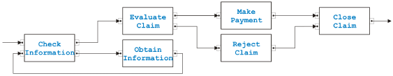
Figure 1: Sequential sample process model A sample process model in the pinset normal form is shown in Figure 1. (It is a slight variation of an example in [13].) The first task called Check Information eventually gets started through the upper arrow on the left side. In order for this to happen, control must be passed from an activity outside that is not shown in the model. The last task called Close Claim passes control after termination through its outgoing arrow to an activity also not shown in the model. Thus, this model is a single-entry-single-exit region because control can be passed in and out only through these two arrows. The sample process models the handling of an insurance claim. The task Check Information determines whether all required information is available. If not, it passes control to the task Obtain Information. This task passes control back to Check Information where again is checked whether all required information has been obtained. This is a loop that could be described as "while there is not enough information available, obtain additional information". When enough information is available, the task Evaluate Claim makes the decision whether payment is made or the claim is rejected. In this example, the two tasks Check Information and Evaluate Claim have two outgoing arrows. Inside these tasks are therefore implicit decisions to determine to which task control is passed. The tasks Check Information and Close Claim have two incoming arrows representing implicit merge control nodes. The arrows representing edges in Figure 1 are not directly connected to the boxes representing nodes but through black dots in small boxes. The dots are called pins and the small boxes pinsets. Because this sample process model is completely sequential, pinsets contain only one pin, but tasks can have more than one pinset on the input as well as on the output side.
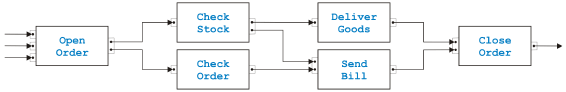
Figure 2: Sample process model with concurrency A second sample process in the pinset normal form is shown in Figure 2. It models an order process. Because of the three edges coming from left, it is not a single-entry-single-exit region. These three arrows represent di erent possibilities to order goods from a company, e.g., via phone call, electronic order form or letter. The task Open Order receives the order and initiates in parallel the two tasks Check Stock to determine whether the ordered goods are on stock and Check Order to make sure, for example, that the person ordering is trustworthy and has always paid the bills. If the test in Check Stock is positive { the sample process shows only the activities related to the positive outcomes of the tests to keep the model simple { and the goods are available, task Check Stock passes control to Deliver Goods. Similarly, if the order is positively checked, the task Check Order passes control to the task Send Bill. The additional edge between Check Stock and Send Bill ensures that the bill is only sent when the ordered goods are on stock and can therefore be delivered. When both parallel activities terminated, i.e., when the goods are delivered and the bill is sent, the task Close Order cleans up. The tasks Open Order and Check Stock have two outgoing edges, and the tasks Send Bill and Close Order have two incoming edges. Here however the pins are in the same pinset because they model concurrency. The pins in the pinsets together with the edges reflect that Check Stock and Check Order as well as Deliver Goods and Send Bill can be executed in parallel, but Send Bill has to wait for the completion of Check Stock before it can start. Generally, two or more pins in an output pinset fork parallel activities and two or more pins in an input pinset join them, but pinsets with more than one pin can also be used for synchronization as in the case of the edge from Check Stock to Send Bill. The behavior of a process model can best be described in terms of token-flow semantics. Tokens can be seen as messages that are emitted at an output pin, transmitted over the edge and stored at the corresponding input pin. (The content of these messages is irrelevant because we do not need to distinguish between control and data flow.) A task starts as soon as all pins in one of its input pinsets have at least stored a token, and consumes one token per pin in this pinset but none of the other tokens that may be stored somewhere else in its input pinsets. When the task terminates, it emits one token through all pins of one output pinset. SoundnessProcess models are assumed to be structurally sound, i.e., every pin is connected to exactly one edge and for each task there is a path from the incoming edge of the process model to this task and further to the outgoing edge. Structural soundness is easy to test. In addition, we only consider process models in the following with one input edge and one output edge, i.e., models that represent single-entry-single-exit regions, and models that contain only tasks with either one or more pinsets with one pin each (or-logic) or one pinset with one or more pins (and-logic) on the input as well as on the output side. The last restriction is not sever because the process models fulfilling it are the ones that can be modeled in the control action normal form, i.e., with decisions, merges, forks, joins and simple tasks [13]. Structurally sound process models of the above kind are called semantically sound if and only if for every possible execution a token transmitted through the input edge eventually causes a token to be transmitted through the output edge and no further tokens are stored in pins of tasks belonging to the process at the time when the token is emitted at the output edge. One consequence of this definition of semantical soundness is that all loops are supposed to terminate sooner or later. More general, we require that every output pinset is activated once in a while, i.e., fulfills the fairness principle. (Otherwise, why would one model pins and edges that are never used?) In a sequential process model only one token exists and is passed from task to task. Because of the requirement that no loops are infinite, it will terminate sooner or later. The more general fairness principle ensures that every edge is taken from time to time. In parallel process models however multiple tokens can exist. In the process shown in Figure 2, two tokens may be emitted by Check Stock when one token may already be pending in an input pin of Send Bill. As already mentioned, structural soundness is easy to test, but what about semantical soundness? How do you determine whether a process model always terminates, and how do you guarantee that at this time no more tokens are stored in some pins? We will answer these questions from two sides. Firstly, we will determine situations that are certainly not semantically sound. If we find one of these situations, we will obviously have to check the corresponding process model very carefully. Secondly, we will define rules to merge tasks where we are sure that they are semantically sound. If in the end a single task with one input and one output pin remains, it must be semantically sound.
Figure 3: Three structural conflicts The three process models in Figure 3 are certainly not semantically sound and represent structural conflicts. The situation in (a) is called lack of synchronization because task D gets two tokens from B and C but only needs one to start. Therefore a token is still in one of the pins when the process terminates. The configuration in (b) is called a deadlock because task D will never start. Only either B or C will get and emit a token but D needs one from both. Also the case (c) is a kind of deadlock that is called parallel cycle because cyclic behavior is only allowed in sequential regions. In order to start, task A needs a token that can only be emitted after it already had started { a kind of chicken-and-egg problem. Structural conflicts in the form of a simple process model as in Figure 3 are clearly not semantically sound. However, if such a situation is part of a larger model, it is not obvious that this model is also not semantically sound. In the case of the parallel cycle, for example, task B may have other incoming edges and thus may get a token independently of A due to the global connectedness of the process. Searching globally for structural conflicts may therefore not be the best method to determine semantical soundness.
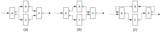
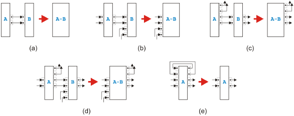
Figure 4: Basic idea of the task-growing rules Instead of a global method, we suggest one that uses only local properties of a process model. Figure 4 shows the basic idea. Two task in a sequence such as A and B in (a) can be replaced by a single task C without changing the token-flow of the process. The only way, a token can reach B is through A. Obviously, task C has now not only to do the job of task A and task B but also in the right order, however, from a token-flow perspective combining the two tasks into one does not change the behavior. The four tasks D, E, F and G can similarly be combined into a single task H because none of the tasks can get a token except through D, and none of the tasks can emit a token to the rest of the process model except through G. If we can handle the two situations in (a) and (b), we can also handle the situation in (c). We first merge the pair J and K, secondly merge the pair L and M, and finally resolve the remaining group. While the transformation in (a) is certainly valid, the situation on the left side in (b) corresponds to the structural error called lack of synchronization. Thus, the transformation step surely is dangerous. In the following, we will first define rules for sequential and parallel situations that we call task-growing rules, but for which we can prove that the resulting task is semantically sound if the tasks that are merged were semantically sound. Merging the two tasks in (a) of Figure 4 is such a rule, but merging the four tasks in (b) is not. We will use the following conventions: One edge from a task to a task means exactly one edge, and two edges from a task to a task mean one or more edges. (Initially, there is only one edge from a task to a task, but later there may be more because of applications of the rules.) Further, if the pinset-structure of a task is irrelevant for a rule, it is just omitted. Sequential RulesThe four rules for merging two neighbors and one rule for eliminating cycles have their roots in the reduction algorithm of [14] and its extension into a goto-elimination algorithm in [7]. The rules for merging two neighbors distinguish di erent cases depending on the other neighbors of the two tasks.
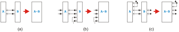
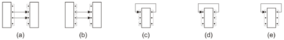
Figure 5: Sequential rules All the sequential rules are shown in Figure 5. The first rule in (a) allows us to combine two connected tasks if the left task A has only outgoing edges going to task B and task B has only incoming edges coming from task A. In other words, this rule removes simple sequences of tasks. The second rule depicted in (b) merges two tasks A and B when all outgoing edges from A go to B but B has incoming connections also from other tasks. The third rule presented in (c) packs two tasks A and B into one when A has outgoing connections to other tasks but all incoming edges of B come from A. The fourth rule shown in (d) handles the most general remaining case of two connected tasks A and B. The last rule presented in (e) removes a so-called self-cycle of a task A. Parallel RulesFor and-logic between two neighbors, there are only three rules corresponding to thefi rst three sequential rules. The fourth rule for parallel edges between neighbors is not needed and would actually not even be valid. A rule similar to the last sequential rule is not allowed because parallel cycles are a structural conflict.
Figure 6: Parallel rules All the parallel rules are shown in Figure 6. The first rule in (a) shows how to combine two connected tasks A and B if all outgoing edges of A lead to B and all incoming edges of B come from A. The second rule presented in (b) merges two tasks A and B if all outgoing edges of A go to B but B has incoming edges also from other tasks. The third and last parallel rule depicted in (c) handles the case of two connected tasks A and B where all incoming edges of B come from A but A has also connections to other tasks. Analysis and TransformationIn terms of token-flow the behavior of the tasks resulting from one of these rules is the same as the behavior of the original tasks, and the rules create only valid tasks from valid tasks. The proof is simple, one just has to determine for all sequential rules whether one token placed on an input pin leads to exactly one token on an output pin without leftover tokens inside the task. For parallel rules, it has to be shown that less than the required tokens on the input side do not lead to tokens on the output side, the required tokens on the input side cause the required tokens to appear on the output side, and there are no leftover tokens after the task terminated. Therefore, if we can transform a process model into a single task with one incoming and one outgoing edge, the original model must be semantically sound. In this sense, the rules can be used as reduction rules to test semantical soundness similar to the intended use of the rules in [11]. If a process model is separable and can therefore be split into a tree of regions with a single entry and a single exit where each region is either sequential or parallel, these reduction rules are not needed because there is an easier way to determine semantical soundness. All structurally sound separable process models are semantically sound [9]. The proof is fairly easy. In a process with only or-logic, there is exactly one token at any point in time during an execution. This token therefore either stays forever in the process or it eventually leaves the outgoing edge. Because there is only a finite number of edges and each edge is taken from time to time due to the fairness principle, the first case is not possible. In a process with only and-logic, exactly one token goes through every edge during one execution.
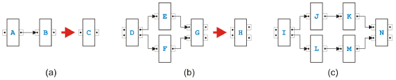
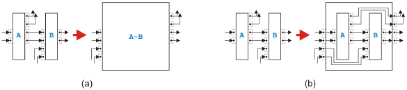
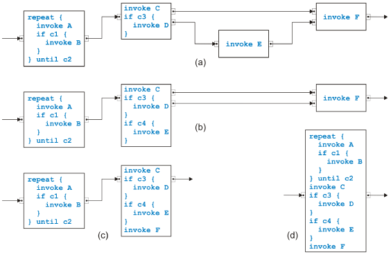
Figure 7: Rule for reduction and for transformation To test semantical soundness of a separable process model, it is therefore sufficient to test structural soundness, and the analysis is trivial. In other words, the task-growing rules are not needed for analysis purposes to determine semantical soundness. They are however very useful for the transformation of the process model into structured form. Figure 7 shows the di erence between a rule used for reduction and for transformation. In (a), the original tasks are eliminated by the reduction algorithm because they are no longer needed, while in (b) the original task structure is kept by the transformation algorithm. The rule used as an example to demonstrate the di erence is the most complicated sequential rule from Figure 5(d). To transform a process model from the graphical, unstructured form into a structured form with textual code, we may not keep the task structure but alternatively assume that some initial code such as invoke A for task A has been assigned to each task. For the transformation of a sequential model, see [15]. We will only show a small example in the following. Because semantically sound parallel models are acyclic, these models can be directly transformed by enumerating all possible paths from the incoming edge to the outgoing edge. The first fork becomes a flow in BPEL that is closed with the last join. All the other timing constraints are in the form task A is followed by task B on a path and become a link in BPEL. Figure 8 shows the first steps of the transformation of the sequential process in Figure 1. Instead of the rather verbose language BPEL, we use a more compact Java-like programming language and write the new code associated with the task
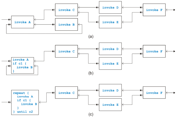
Figure 8: Sample transformation part 1 after the rule has been applied directly into the boxes representing tasks. The conditions c1 and so on in the if-statements are composed of the conditions inside a task to determine which of the output pins is used to emit a token. The initial process (with simpler names) is shown in (a). The lower two tasks are merged in (b), and the such created self-cycle is removed in (c). The second part of the transformation is shown in Figure 9. The task called Evaluate Claim in the original process swallows first its upper neighbor in (a), then its lower neighbor in (b) and afterwards the new neighbor in (c). The final result after merging the remaining two tasks is presented in (d). Crucial properties of transformations of the kind shown here are correctness and completeness of the rules. Of similar importance is confluence, i.e., the in confluence of the the rule application sequence. We already discussed the correctness shortly. Completeness for the sequential rules is obvious because every edge in a process model except for the incoming and the outgoing edge connects two tasks. If these tasks are two di erent tasks, one of the first four rules covers the situation. If the two tasks are the same, the edge must build a self-cycle and is removed with the last rule. Completeness of the parallel rules can also easily be shown. Because there are no cycles, there must be a path from the task with the incoming edge to the path with the outgoing edge that has maximal path length. The first task and its successor on this path can be merged. The set of rules is not confluent in the sense that every application sequence results in the same code, but is confluent in the sense that all possible results are
Figure 9: Sample transformation part 2 equivalent. If the rule that removes self-cycles has high priority, many repeat-loops may come out. If however this rule has lowest priority, at most a single loops will be created. The preconditions for all rules for two neighbors match di erent situations except for the simplest sequential and the simplest parallel rule in the case that task A has one output pinset with one pin and task B has one input pinset with one pin. (One pinset with one pin can be interpreted as or-logic but also as and-logic.) In this case, it is convenient to give the sequential rule higher priority. To summarize, we can transform any separable process model in this way from its graphical, unstructured form into structured, textual code. A process model is split into a tree of single-entry-single-exit regions, and the leaves of this tree are transformed from inside out, i.e., bottom-up. A transformed region becomes a single task in the parent region. 3 MIXED PROCESS MODELSNot all semantically sound process models are separable. We discuss the overlapped pattern, the rules from [9] to handle it and present di erent rules. The Overlapped Pattern Most process models are in fact separable, but there is the overlapped pattern introduced
and discussed in [11] that mixes or-logic with and-logic in a way that it its resolution into an equivalent separable process model needs duplication of certain
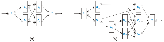
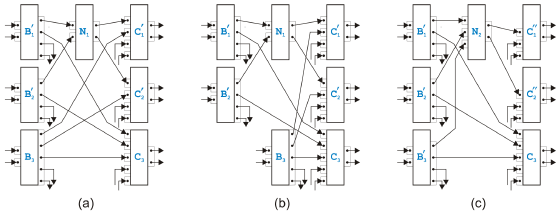
Figure 10: Two examples of an overlapped pattern Two di erent examples of overlapped patterns are presented in Figure 10. The model in (a) is the simplest possible case. Task A sends either a token to B1 or B2. Each Bi sends a token to each Cj such that task D gets all the tokens it needs to terminate. The kernel of an overlapped pattern are n tasks Bi (with n ≥ 2) and m tasks Cj (with m ≥ 2). They have or-logic on the input side and and-logic on the output side. Exactly one edge goes from every Bi to every Cj . The model in (b) is more complex but still based on the same basic pattern. The set of rules defined in [9] to transform process models matches the kernel of an overlapped pattern with n tasks Bi and m tasks Cj such as in Figure 10(a), but cannot handle the example in Figure 10(b). The reason is actually quite obvious. In the proof in [9] that the overlapped pattern is the only case where a process model is not separable, the fact is used that control nodes with more than two outgoing or incoming edges can be split without changing the behavior of the process. The same possibility is needed to resolve the process model in Figure 10(b).
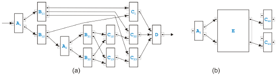
Figure 11: Transformed overlapped pattern example Figure 11 shows how this example of an overlapped pattern can be handled after splitting C2 and C3. In (a), the process model after the split is presented, and in (b), only th part of the model is shown where the kernel of the overlapped pattern has been packed into the new task E as the original rule in [9] would have done. Note that E has or-logic on the input side and and-logic on the output side. Note also that this example process model can now be transformed with the sequential and parallel rules introduced in the last section into another overlapped pattern with two tasks Bi and three tasks Cj. Mixed RulesFor the mixed regions, we introduce sixteen new rules. It is actually only one rule that comes in sixteen flavors.
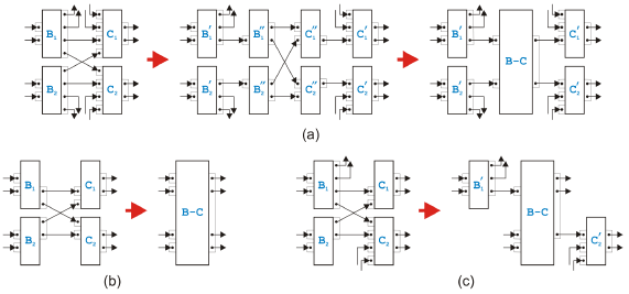
Figure 12: Mixed rules Figure 12 presents the most complex variant of the mixed rules and two simpler cases. The sixteen subrules come from the fact, that the tasks Bi can have other outgoing edges that are not part of the overlapped pattern, and that the tasks Cj can similarly have other incoming edges. The most complex variant of the rule with a virtual intermediate state is shown in (a). All four tasks belonging to the kernel of the overlapped pattern must be split into two tasks. The subrule in (b) depicts the simplest case where none of the tasks need splitting. The subrule (c) is one example of the remaining variants. For the or-logic on the input side of the tasks Bi and the and-logic on the output side of the tasks Cj remember that a single pinset with a single pin can be interpreted as or-logic or as and-logic. Discussion of Alternative RulesThe rule proposed in [9] for handling parts of a process model where or-logic and and-logic cannot be separated searched for structures with n tasks Bi and m tasks Cj that build the kernel of an overlapped pattern. As just discussed, this is not sufficient to cover all situations possible in semantically sound process models. In order to extend the original rule, we could have defined the mixed rules di erently: Instead of the rule in Figure 12(a), we could have either introduced a similar but more general rule with n tasks Bi and m tasks Cj, or we could have left the original rule the way it was originally defined but have added a separate rule for splitting the tasks Bi and Cj. Both alternative solutions have advantages and disadvantages. The first alternative set of mixed rules would be able to handle on one hand rather complex situations in one rule, but on the other hand, it is not easy to match the required maximum patterns when tasks can be splitted. In addition, we tried tofi nd "atomic" rules, i.e., rules that are as simple as possible but still cover all possible situations in semantically sound process models. (Nothing speaks however against resolving the overlapped pattern with such a complex rule when implementing an analysis or transformation algorithm based on the rules proposed in this paper. Matching patterns as large as found may be sufficient.) The second proposal to have separate rules for the overlapped patterns and the splitting of tasks seems to be even closer to our philosophy of having "atomic" rules than the rules we introduced. Actually rules for splitting tasks and a rule for handling overlapped patterns with only two tasks Bi and two tasks Cj would be the most "atomic" set of mixed rules. Such an approach has however a very severe disadvantage. The rules for splitting tasks increase the number of tasks and the number of edges. In addition, there are sequential and parallel rules to undo this splitting. In other words, there are infinite sequences of legal rule applications which split and merge tasks forever without terminating. This is the reason why we allow the splitting of tasks only to achieve a virtual state before the overlapped pattern is resolved where it cannot spoil termination. Termination, Correctness and CompletenessEach of the sequential and parallel rules reduce the number of edges at least by one. With the exception of the rule for the self-cycles, they also remove one task. Application of an algorithm based on these rules is therefore guaranteed to terminate, because a process model contains only a finite number of tasks and edges. The situation for the mixed rules is not as trivial because the most complex variant increases the number of tasks by one and keeps the number of edges constant. The other variants however do not increase the number of tasks and even decrease the number of edges at least by one. The worst case that could prevent the application of the rules from terminating would therefore be a process model where the most complex variant of the mixed rules can be applied infinitely often. In each step, a new task would be created but the number of edges would stay the same. This is obviously not possible without the process model breaking sooner or later into unconnected pieces. Correctness of the mixed rules can be demonstrated in a similar way as the correctness of the sequential and parallel rules but the proof may have to be broken up into two steps. In the first step it is shown that splitting tasks into two does not change the token-flow. In the second step the same is shown for the four tasks that build the kernel of the overlapped pattern and that are merged into one task. With the rules in Figure 12, an overlapped pattern with n tasks Bi and m tasks Cj can be resolved. We prove this assertion using induction over n or m, respectively. Every task Bi has m outgoing edges, one to every task Cj, and every task Cj has n incoming edges, one from every task Bi. We show how we can use the mixed rules to get an overlapped pattern still with n tasks Bi but only m - 1 tasks Cj. (The proof for decreasing n instead of m is very similar.) When we apply the mixed rules, some of the tasks get split into two tasks of which one gets merged with the kernel of the overlapped pattern into a new task while the other one remains as an individual task. We will treat the original and the remaining task as the same task. This slightly sloppy interpretation is convenient because we can handle the initial tasks of the process model as a more or less constant set whose elements are modified through the transformation steps.
Figure 13: Some steps in a proof We start with an overlapped pattern with n Bi and m Cj from which we select two tasks from one group, say B1 and B2, and two tasks from the other group, say C1 and C2. The most complex mixed rule is applied to these four tasks and the new task N1 is created. The next two steps are shown in Figure 13 together with the result of this application of the mixed rule presented in (a). In (b), the next step is prepared by selecting N1 and a not yet used Bi, say B3, together with the remainings of the previously used C1 and C2. We apply a variant of the mixed rule again to get N2, and the result is depicted in (c). (Note that N2 does not have to be split, because it has only the two outgoing edges to C1 and C2.) We continue this way, select a not yet used Bi and apply a mixed rule to it together with the result of the previous step and the remainings of C1 and C2. Every Bi loses one output pin, Nk gains one input pin and C1 and C2 lose one input pin each. After n - 2 steps, there is only one untouched Bi left, and C1 and C2 have only two remaining input pins with edges coming from this Bi and from Nk. These four tasks build an overlapped pattern, but when the corresponding mixed rule is applied, C1 and C2 will not split. We have reduced the process model by the two tasks C1 and C2, have gained a task Nk with n input pins connected to every Bi and can therefore rename Nk to C2. This proves that the set of mixed rules can at least resolve the same process models as the rules in [9]. Together with the example presented in Figure 11, the set of rules can actually handle more, but the obvious question arises whether the set of sequential, parallel and mixed rules introduced above is now really complete. 4 ARBITRARY PROCESS MODELSThe set of rules introduced in this paper can be used to analyze arbitrary structurally sound process models for semantical soundness and, when semantically sound, to transform them into a structured form. AnalysisIn the following, we assume that all process models have exactly one input and one output edge, are structurally sound, fulfill the fairness principle and are in pinset normal form with tasks that have, on the input as well as on the output side, either one pinset containing one or more pins or one or more pinsets containing one pin. We apply the set of sequential, parallel and mixed rules without splitting the processfi rst into a tree of single-entry-single-exit regions and see what happens. Simpler rules are supposed to have higher priority than more complex rules. The rule in Figure 5(b), for example, is only applied if the rule in Figure 5(a) cannot be applied somewhere in the process model. When no rule can be applied anymore, the process model has either been reduced to a single task with one input and one output edge, or it still contains additional tasks and/or edges. In the first case, the process model has been shown to be semantically sound. In the second case, the process model is either not semantically sound or the set of rules proposed in this paper is not complete.
Figure 14: Unresolvable situations Figure 14 shows five situations in which the reduction algorithm based on our set of rules would get stuck. If two or more edges lead from a task with and-logic on the output side to a task with or-logic on the input side as in (a), we have a structural conflict called lack of synchronization, and if two or more edges lead from a task with or-logic on the output side to a task with and-logic on the input side as in (b), we have a deadlock. If the output and the input pinset in these two cases belong to the same task, i.e., if there is a self-cycle, a single edge is sufficient for a lack of synchronization as in (c) or for a deadlock as in (d). If the self-cycle connects and-logic with and-logic as in (e), there is a parallel cycle. Note that the structural conflicts in Figure 3 have become local properties of a single task or between two neighboring tasks. If no rule can be applied anymore due to one of these five situations, the process model is obviously not semantically sound, and the termination of the reduction algorithm was justified. But can it happen that the reduction algorithm stops on a semantically sound process? To prove that the set of rules is complete, we look at the proof of Lemma 3 in [9]. This lemma states that if a semantically sound process model is not separable, it contains an overlapped pattern. We start from a semantically sound process model and apply the sequential and parallel rules until none of these rules can be applied anymore. If the resulting process model consists of only one task with one incoming and one outgoing edge, the original process model was separable. Otherwise, we got stuck in a process model that is still semantically sound. The proof of Lemma 3 starts from the outgoing edge of the process model and determines, arguing backwards, that there must be an overlapped pattern (after possibly some splits of forks) if the process model is semantically sound and if none of the sequential and parallel rules can be applied anymore. The proof basically shows that there must be a pattern of the form on the left side of one of the mixed rules. The corresponding rule can be applied, and the process model is obviously still semantically sound. Therefore, the sequential and parallel rules can be applied until the reduction algorithm stops again. If the process has not been reduced to a single task with one incoming and one outgoing edge, we apply the argument in the proof of Lemma 3 again. Thus, sooner or later the process model is reduced to a single task with one incoming and one outgoing edge. The set of sequential, parallel and mixed rules is therefore complete. TransformationWhen using the rules as reduction rules to determine the semantical soundness of a process model, we applied them on the model without building the tree of singleentry-single-exit regions first. When using the rules as transformation rules to bring the model into structured form, there are however reasons to build this tree first.
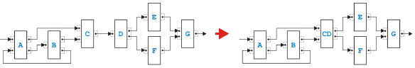
Figure 15: Rule application leading to a mixed region The first reason is related to processing speed. If a process model is large, one would like to make use of today's multi-processor computers and run as much of the transformation in parallel as possible to get the result quickly. Because the di erent regions in the tree are independent, they can be transformed concurrently. The second reason is illustrated in Figure 15. The simplest rule in the sequential and the parallel set can merge the two tasks C and D such that the two previously separable regions, i.e., the sequential region on the left side and the parallel region on the right side, become one mixed region. Since the transformation into structured code, as discussed above, can be done di erently on sequential and on parallel regions, we would like to avoid mixed regions whenever possible. Creating the tree of single-entry-single-exit regions before starting the transformation can avoid mixed regions if the process model is separable. If the model contains overlapped patterns, the result of the transformation however will unavoidably include mixed regions. In the following, we show how such a mixed region can be turned into an equivalent separable region by duplicating certain tasks. We name the tasks the same way as in [16] to make the comparison of our conversion with the original conversion easier.
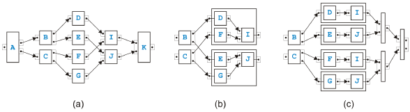
Figure 16: Resolution of an overlapped pattern Figure 16 shows some steps of the conversion. In (a), the initial situation is shown as in [16], where it is called "overlapping structure" instead of "overlapped pattern". The sequential and parallel transformation rules merge the tasks D, E, F and G either with B and C or with I and J. In (b), the configuration is shown when none of the sequential and parallel rules can be applied anymore. (Without loss of generality, we assume that the above mentioned tasks have been merged with their successors.) We only show the kernel of the overlapped pattern, because the mixed rules pack the kernel into a new task and we do not know what happens to the rest of the process model. The result of the conversion with the replicated tasks is depicted in (c). The duplications disentangle the successors of task B and task C and make them independent. The additional empty tasks are needed to make sure that the output logic of the converted kernel is compatible with the input logic of the task K or whatever the tasks I and J are connected to. The result without the last empty task on the right side consists of an upper and a lower part, and both these parts build independent regions. Converting the kernel of an overlapped pattern into separable regions by duplicating tasks can therefore eliminate mixed regions. Due to the duplications, neither the conversion itself nor the result is particularly elegant, but, luckily, overlapped patterns are more an academic puzzle than a real problem. 5 SUMMARYA large group of business processes and work flows is modeled graphically as a directed graph where edges have a similar function as goto-statements in programming languages. They specify behavior therefore in an unstructured form. Analysis to determine semantical soundness of these models and transformation to bring them into a structured form ready for deployment can be done with a set of rules that can be either used as reduction rules or as task-growing transformation rules. The set of rules presented here is correct and complete, the reduction or transformation algorithm based on them is guaranteed to terminate, and the rules can handle the overlapped pattern in its various forms. The transformation algorithm is therefore able to detect when a process model specified in a graph-based modeling language such as UML Activity Diagrams or BPMN is not semantically sound, may suggest corrections and can finally compile the semantically sound process model into code of a structured programming language such as BPEL. REFERENCES[1] W.M.P. van der Aalst, "The Application of Petri Nets to Workflow Management",J. of Circuits, Systems and Computers, 8(1), 21-66, February 1998. [2] OMG Unified Modeling Language (UML), http://www.uml.org/. [3] OMG Business Process Modeling Notation (BPMN), http://www.bpmn.org/. [4] C. Bock, "UML 2 Activity and Action Models", J. of Object Technology, 2(4), 43-53, July-August 2003, http://www.jot.fm/issues/issue 2003 07/column3/. [5] IBM WebSphere Business Modeler (Business Process Modeling Software), http://www.ibm.com/software/integration/wbimodeler/. [6] OASIS Web Services Business Process Execution Language (WSBPEL) TC, http://www.oasis-open.org/committees/tc home.php?wg abbrev=wsbpel. [7] Z. Ammarguellat, "A Control-Flow Normalization Algorithm and Its Complexity", IEEE Trans. Software Engineering, 18(3), 237-251, 1992. [8] W.M.P. van der Aalst and K.B. Lassen, "Translating Unstructured Workflow Processes to Readable BPEL: Theory and Implementation", Information and Software Technology, 50(3), 131-159, February 2008. [9] R. Hauser, M. Friess, J.M. Küster, and J. Vanhatalo, "An Incremental Approach to the Analysis and Transformation of Workflows using Region Trees", IEEE Trans. Systems, Man, and Cybernetics - Part C, 38(3), 347-359, May 2008. [10] R. Johnson, D. Pearson, and K. Pingali, "The Program Structure Tree: Computing Control Regions in Linear Time", PLDI 1994, ACM Sigplan Conference on Programming Language Design and Implementation, 171-185, 1994. [11] W. Sadiq and M.E. Orlowska, "Analyzing Process Models Using Graph Reduction Techniques", Information Systems, 25(2), 117-134, April 2000. [12] J. Vanhatalo and H. Volzer, private communication, August 2007. [13] J.M. Küster and M. Abd-El-Razik, "Validation of Model Transformations - First Experiences Using a White Box Approach", MoDeVa 2006, 3rd Workshop on Model Design andValidation, LNCS 4364, 193-204, 2007. [14] M.S. Hecht and J.D. Ullman, "Flow Graph Reducibility", SIAM J. Comput., 1(2), 188-202, 1972. [15] R. Hauser and J. Koehler, "Compiling Process Graphs into Executable Code", GPCE 2004, 3rd International Conference on Generative Programming and Component Engineering, LNCS 3286, 317-336, October 2004. [16] R. Liu and A. Kumar, "An Analysis and Taxonomy of Unstructured Work-flows", BPM 2005, 3rd Conference on Business Process Management, LNCS 3649, 268-284, 2005. About the author
Rainer Hauser: "Analysis and Transformation of Behavioral Models Containing Overlapped Patterns", in Journal of Object Technology, vol. 9, no. 3, May-Junel 2010, pp. 105-124 http://www.jot.fm/issues/issue_2010_05/article4/ |
||||||||||