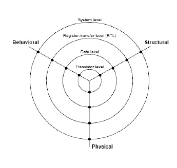
AbstractRecent embedded systems and SOCs design is confronted with the problem of the so-called productivity gap. In order to cope with this problem, authors emphasize on using UML as a system level language, so higher level of abstraction is achieved. However UML in its current form has not yet achieved the maturity necessary to enable its efficient use within current embedded systems and SOCs CAD environments. Consequently a proper tuning of UML to the specificities of such systems has become mandatory. To meet this requirement, many UML profiles have been proposed by both academia and industry. On the other hand enhancements included in UML2.0 has increased UML opportunities to model embedded systems. UML2.0 is qualified to be a component-based which is more suitable for hardware modeling. In this paper we review and compare the most known UML2.0 profiles for embedded systems and SOCs. For each profile, we try to show its defined stereotypes and the corresponding design flow if it exists. We use some objective criteria to highlight the benefits and the pitfalls of each profile. 1 INTRODUCTIONThe productivity gap between semiconductor technology and methodology and tool support has became one of the biggest challenges in embedded systems and SOCs design. To deal with this problem, specialists in the field have resorted to software engineering and borrowed from it many ideas to close this gap. Most of authors are agree on at least five principles that are raising the level of abstraction, hierarchy, separation of concerns, reuse, and integration. Since embedded systems and SOCs development requires collaboration between customers, software and hardware teams, a visual common language is preferable to eliminate misunderstandings that can occur. This language must be able to capture customer requirements and then proceeds toward an efficient software and hardware implementations in a well defined design flow supporting the five principles mentioned above. We believe that if done correctly, the Unified Modeling Language (UML) can be such a language. UML2.0 has brought several significant improvements to support concepts related to Codesign.The latter aims at meeting the system-level requirements by using a concurrent design and validation methodology, thus exploiting the synergism of the hardware and the software parts. Although software (Sw) design techniques may seem foreign to hardware (Hw) designers, at a reasonable level of abstraction such separation can be blurred because many of concepts are similar. For instance Sw objects communicate with messages and Hw blocks communicate with signals. Sw systems reuse classes from libraries and Hw systems reuse IPs (intellectual properties). Embedded systems (ES) are generally defined as application-specific computers, masquerading as non-computers that interact with the physical world and must perform a small set of tasks cheaply and efficiently. ES have specific characteristics such as heterogeneity (hardware / software), ability to react, criticality, real-time and consumption constraints. As the resources are constrained, the design of embedded systems requires optimization. According to Moore 's law stipulating that the integration density of VLSI circuits doubles all the eighteen (18) months, embedded systems will contain more one billion of transistors in the near future. Modern ESs are capable to execute very complex algorithms implemented in only one chip (SOC: System-on-a chip). A SOC is a complex and heterogeneous system that can integrate in the same chip hundreds of IPs possibly furnished by different manufactures and connected by communication infrastructure ranging from simple buses to complex On chip networks (NOC: Network On Chip). A general classification of the design process of embedded systems is available through the DajskiY-Chart as shown in Figure 1. It defines System, Register-Transfer (RT), gate, and transistor levels where each level is defined by the type of objects and where higher level objects are hierarchically composed out of lower level ones. At each level, the design can be described in the form of a behavioral, a structural model, or a physical model. A conventional design process (see figure 2) starts from informal requirements; a functional executable model (eg. C/C++) is modelled from the requirements to capture the system behaviour. At this level there is no difference between software and hardware parts. The final destination of the various parts of the design are decided at the partitioning stage. Two separate design flows start concurrently for the software and hardware. Software parts are compiled for the target processing elements and hardware parts are translated to an HDL (Hardware Description Language) description, then synthesized into ASICs or FPGAs. Intermediate steps of functional and timing verifications and simulations are carried out at different phases. Today ‘s methodologies fail to meet embedded systems requirements. This is due essentially to the large gap that exists between the specification level and the implementation level on one hand and because the hardware and software teams are still work independently and the actual hardware-software integration takes place lately where discovered errors are often uncorrectable.
Figure 1: The Y-chart model of Gajski [9]
Figure 2: Conventional SOC design flow [15] 2 UML2.0 AND HARDWARE DOMAINUML is a graphical object-oriented modeling language, originally, was used in software (information) systems. The use of such graphical notation help designer to understand, capture and analyze the client requirements at early stages of development in a semiformal manner. In its basic form, it is applicable to a wide variety of systems (open language). However, several key attributes of UML are important to embedded systems:
Beyond UML1.x deployment diagram, StateChart and sequence diagram which had even used to model hardware resources and their topology, to synthesize FSM controllers, and to model hardware communication protocols (eg. Handshake) respectively, UML2.0 includes two new diagrams more suitable to represent hardware concepts that are the structure diagram (SD) and timing diagrams (TD). The SD describes the structure of the system as a network of components (objects, composite objects and blocks) related by channels (links). It is similar to the well known functional block diagram used in the hardware domain. Components are associated with ports defining required and provided interfaces and communicate via signals. We can consider The TD as a chronogram which is used to represent signal progression over time. The new semantics attached to activity diagrams (data flow) are also important to model the Datapath of the processing units. New features included in UML2.0 sequence diagrams (eg. Control flow, hieararchy, timing constraints) are also important for SOCs performance analysis [21]. Recent works aim at generating hardware description languages like VHDL [20], and SystemC from UML diagrams [15]. The generated code is used either for simulation or synthesis purposes. Despite of the effort in the direction of UML-based system-level design, there is no consistent design flow for embedded and SOCs systems and the proposed methodologies and associated tools still lack completeness and interoperability. For this reason, many UML2.0 profiles have been proposed by both academia and industry. According to authors,UML2.0 can be tailored to different application domains by the definition of profiles. A profile extends an application specific UML sub-set using extension mechanisms offered by UML like stereotypes, constraints, and tagged values. Further more a profile must provide a methodology. 3 SYSMLThe System Modeling Language (SysML) [18] is the resullt of a joint initiative of OMG and the INCOSE (International Council on Systems Engineering). It reuses a subset of UML 2.0 and provides additional extensions needed in system engineering. SysML supports the specification, analysis, design, verification and validation of a broad range of complex heterogeneous systems which are not necessarly software based. It is intended to unify the diverse modelling languages currently used by systems engineers. As shown in figure 3, the set of UML metaclasses to be reused are merged into a single metamodel package called UML4SysML. The SysML profile can be applied by a user model either "strictly" where, only the UML metaclasse referenced by SysML are available to the user of that model or "not strictly" where additional UML metaclasses which were not explicitly referenced may also be available.
Figure 3: SysML architecture [18] SysML introduces two new diagrams (Figure 4): the Requirement diagram and the Parametric diagram. A requirement diagram allows the system engineer to model requirements and relating them to other model elements that satisfy or verify them ( figure 5). The parametric diagram is used to model systems parameters and relate them to each other. Block definition, Internal Block, and Activity diagrams are similar to the UML2.0 class diagram, composite structure diagram, and activity diagram respectively, with some extensions. We note especially the concepts of assembly and flowPort for composite diagrams, and the actions execution control mechanism for activity diagrams (eg. Running actions can be disabled). SysML does not use UML object diagram, communication diagram, interaction overview diagram, timing diagram, and deployment diagram. In the case of deployment diagrams, the deployment of software to hardware can be represented in the SysML internal block diagram using the concept of allocation which is a more abstract form from UML deployment [20].
Figure 4: SysML diagram taxonomy
Figure 5: SysML Requirements 4 MARTE (MODELING AND ANALYSIS OF REAL TIME EMBEDDED SYSTEMS)Defined by the ProMARTE Working Group and is voted at OMG for the Model-Driven Development (MDD) and analysis of real time and embedded systems, MARTE [16] intends to replace the existing UML-SPT profile. It is based on the UML2.0 Metamodel, OCL2, and MOF 2.0 QVT. As illustrated by Figure 6, the MARTE architecture is focused on four packages: the MARTE foundations, the MARTE design model, the MARTE analysis model, and the MARTE annexes. The MARTE foundations package includes the NFPs profile for Non-Functional Properties modelling which is one of the main capabilities of this profile. An NFP (see figure 7), can be either basic or complex, qualitative or quantitative. An NFP value can be specified as a constant value (NFP Constant), as a variable (NFP Variable) or as an expression (NFP Expression), the TIME profile for logical and physical time modelling and related concepts, the GRM profile for Generic Resource Modelling. The GRM is detailed via DRM for Detailed resource modelling, the GCM profile for Generic Component Modelling, and the ALLOC profile for application-hardware mapping. The MARTE design model package represents the profile core, it encompasses the RTEMOCC profile for real time model of computation and communication. The latter is based on the Runit concept, which combines between object and process paradigms, the SRM profile for Software Resource modelling, and the HRM profile for Hardware Resource Modelling. The MARTE analysis package introduces common elements that can be used in providing input to many kinds of quantitative analysis. Three particular types of analysis are considered, The Schedulability Analysis Modeling (SAM), the Performance AnalysisModeling (PAM) and the WorstCaseExecution TimeAnalysisModeling. The MARTE annexes package includes in particular the VSL subprofile for Value Specification Language which is an expression language, used to specify non-functional values, and the RSM sub-profile for repetitive structure modelling.
Figure 6: Architecture of the MARTE profile [16] MARTE brings many benefits since it provides support for specification, analysis, design, and verification/validation stages, provides a common way of modelling both hardware and software aspects of a real time embedded systems in order to improve communication between developers, and fosters the construction of models that may be used to make quantitative predictions.
Figure 7: Example of user model with NFPs and VSL [16] 5 UML-SOCIt is developed by Fujitsu Limited and Fujitsu Laboratories. A related OMG submission [17] was prepared by a consortium consisting of Fujitsu Limited, IBM Corporation, CANON INC., CATS Co., Metabolics Ltd., RICOH COMPANY LTD., and Toshiba Corporation. This profile intends to describe System-On-Chip specific information using UML. It integrates concepts from SOCs and allows automatic code generation for hardware (eg. SystemC), covering abstraction levels from Transactional Level Modelling (TLM) to Register Transfer Level (RTL). UML-SOC is focused on the UML2.0 structure diagram. It proposes the stereotypes that allow the structural modelling, communication modelling, operation and property modeling. Table 1, gives correspondance between some SOC stereotypes and UML constructs.The motivation for the profile is that UML defines many types of diagrams but does not describe how to use them. The decisions concerning the part of the specification to be modeled and the diagrams to be used as well as how to model the specification with different diagrams must be made. In this approach UML is used as a formal model for the specification of the SoC design to allow the validation of the consistency and completeness of the specification (see figure 8). The consequent SoC implementation is validated by a systematic derivation of test scenarios from the UML model. UML is integrated into the verification process without changing the current design style. Only use case diagrams, sequence diagrams and class diagrams of UML are utilized in modelling of functions, data types and behaviors in the specification. Interfaces in SoC cannot be modeled simply by operations and methods. Instead, a proprietary Component Wrapper Language (CWL) as a formal interface specification language is used to model the specification of signal changes at input/output ports [22].
Table 1: A Sub-set of the UML-SOC profile stereotypes [17]
Figure 8: UML- SOC profile flow [22] 6 UML-SYSTEMCThis profile is developed by University of Catania and STMicroelectronics [15]. It takes advantages of both UML2.0 and SystemC language following the MDA principles. SystemC is well suited for implementing UML models, since it supports object-oriented paradigm and can uniformly represent hardware and software in a single language. Furthermore, as UML, SystemC is becoming the standard system level language for SOCs design. According to [15], UML may improve the SOC design flow in three ways:
The UML-SystemC profile captures both the structural and the behavioral features of the SystemC language and allows high level modelling of SOCs with straightforward translation to SystemC code. It is based on two diagrams: classes diagrams to model structure and statecharts to model behaviour. The most significant stereotype elements used in various UML structural diagrams represent the structural building blocks of SystemC such as module, port, interface, primitive channel, hierarchical channel, thread process and event. Figure 9, shows the correspondence between SystemC and UML concepts. The proposed profile is believed to benefit greatly the portability, interchange, and reuse of the IPs.
Figure 9: UML notation for SystemC concepts [15]
Figure 10: UML –SystemC based SOC design flow 7 TUTIt is developed in the Institute of Digital and Computer Systems at Tampere University of Technology (TUT), the TUT Profile is an UML2.0 profile for multi-processor SOCs design [13]. It classifies different application and platform components by defining various stereotypes and strict rules how to use them. The objective is to enhance the support of external tools for automatic analyzing, profiling, and modifying the UML2.0 description of an embedded system. The classification also assigns defined parameters to proper components. Using this profile application is modelled as a network of processes following the Kahn Process Network (KPN) semantics. Each process behaviour is modelled via a statechart. The platform description is not used for hardware synthesis, rather than, it represents an abstraction of an available parametrized RTL components library. The mapping is defined by the stereotype "PlatformMapping". It is applied to describe how a process group is mapped to a platform component. The methodology is realized with the Koski design flow (figure 11). The platform mapping can be explicitly performed by the designer, or assisted with tools. In the latter case, an UML profiling tool that combines the UML2.0 description and simulation statistics that is obtained the verification phase is developed. Based on the profiling results, the application can be modified to fulfill real-time constraints. When the verification is completed, executable application for the implemented platform is automatically generated from the UML2.0 description. The TUT profile provides an automated path from UML design entry to FPGA prototyping including the functional verification and the automated architecture exploration focusing on automatic profiling and performance values back annotation.
Table 2: TUT profile stereotypes summary
Figure 11: Koski design flow [13] 8 GASPARD2Developed by the DaRT (Dataparallelism for Real-Time) team of LIFL (Laboratoire d'Informatique Fondamentale de Lille- France), the Gaspard2.0 is an UML2.0 profile that targets the intensive signal processing domain [4]. It follows the MDA principles and emphasizes system level co-modelling and concurrency, separation of concerns (communication vs computation, data vs control, application vs architecture), simulation, models refinement, automatic code generation (eg. SystemC, VHDL, JAVA) and IP integration. Gaspard2.0 profile extends the UML2 semantics to allow the user to describe a SoC at different level of abstractions in three steps: the application, the hardware architecture, and the association of the application to the hardware architecture. Figure 12: Gaspard packages [4] The gaspard2.0 profile includes six main packages (see figure 12), that are the component, the factorization, the hardwareArchitecture, the application, the control, and the association. In Gaspard, application is modelled using three models of computation that are: KahnProcessNetwork (KPNs) to model computational tasks using the GaspardComponent and GaspardPort stereotypes (component package). The former can be elementary, hierarchical or repetitive, Array-OL to express in a compact way the topologies of relations and dependencies between multi-dimensional arrays of connectable elements (factorization package), and synchronous reactive programming (Esterel, Lustre) to model reactivity and control related aspects via automata (Control package). The principles of application metamodel are based on the ISP UML profile that allows the expression of task and data parallelisms [6]. HardwareArchitecture describes hardware resources and their topologies at a cross grained level. The goal of the association is to provide tools that bind an application to a hardware architecture. They mainly consist in mapping tasks to active components and mapping data to memories, while handling hierarchy and repetitions.
9 DIPLODOCUS (DESIGN SPACE EXPLORATION BASED ON FORMAL DESCRIPTION TECHNIQUES, UML AND SYSTEMCtechniques)Is an UML2.0 profile based on the TURTLE UML profile targeting SOCs domain [2]. it is focused on four aspects:
DIPLODOCUS UML profile focuses on design space exploration. Its strength relies on transformation rules that make it possible to automatically transform DIPLODOCUS modelings either in SystemC, for simulation purpose, or in a LOTOS specification. Before simulation is done, each task behaviour which is modelled via an activity diagram is transformed to an equivalent behavior expressed in a simple language called TML (Task Modeling Language) [1]. This language abstracts data exchange, data processing and control exchange using coarse-grained instructions. There is no data processing details inside the tasks. They are only control oriented without any notion of physical time. However operations within a task model are totally ordered and among a set of tasks, they are partially ordered. The functional simulation is achieved by translating TML instructions to corresponding SystemC constructs.
Figure 14: Semantics of various operators of DIPLODOCUS activity diagrams [2]
Figure 15: Methodology adopted by DIPLODOCUS [1] 10 UML PLATFORMDeveloped by the University of California at Berkeley, the UML platform targets the domain of wireless protocols [5]. It is based on UML2.0, and the UML Real Time. Since the UML Platform profile follows the platform-based design, it defines stereotypes for application, platform, mapping, and refinement. In this profile application is modelled as a processes network using standard MoCs (Models Of Computations) such as Kahn Process Networks, Synchronous Dataflow etc. and elementary building blocks, such as buffers, and protocols that can be used to specify a MoC. The behavior of individual components is specified using State Machine, Activity Diagrams, or textual notation. The Platform model includes many kind of stereotyped components such as physical and logical resources, services offered by resources, QoS constraints, and relations between resources, services and service users stereotyped by UML Real-Time and UML Platform profiles. The semantics of UML Platform is defined in terms of the Metropolis Metamodel by establishing a direct correspondence between modeling elements of UML Platform and elements of the Metropolis Metamodel.
Figure 16: Stereotyped relationships The design methodology, based on the UML Platform profile and Metropolis, is shown in Figure 17. In the first step the design problem is formulated using Use Case diagrams, and the constraints are annotated to the model, then, the functionality is decomposed into components and captured using the UML Platform stereotypes. Constraints are propagated and budgeted to the components. The Metamodel functional specification can be validated using the Metropolis simulator. As a next step, the UML Platform specification is compiled into a Metropolis Metamodel specification. Then, Communication Refinement and Mapping take place. The UML Platform model is compiled into a mapped Metamodel specification, and performance analysis and validation take place in the Metropolis simulation environment (figure 17).
Figure 17: UML Platform Design Flow [5] 11 DISCUSSIONIn this section, we try to highlight in some detail the limitations of each profile. A full comparison is showed in table 3. SYSMLWith regard to embedded systems and SOCs particularities, there are strong similarities between the methods used in the area of System Engineering and complex SOC design, such as the need for precise requirements management, heterogeneous system specification, simulation, verification, and validation [20]. One of the major contributions of SysML in the area of ES and SOCS is the support for requirements modeling (see figure). The main limitations of SysML are not in the early design phase, but become clear as the design is refined towards the Software/Hardware implementations. On the other hand, SysML does not solve the question of the lack of semantics in UML2.0 and does not dictate any particular development process to be used. In order to be able to integrate SysML requirements models in embedded systems and SOCs design flows, formalization of such informal annotations is required. MARTEMARTE targets mainly real time embedded software-dominated systems. This profile offers a facility for modelling and analyzing real time applications, however in the Codesign context, where hardware and software developments often take place simultaneously, the profile becomes less useful: Hardware related problems like, design space exploration, synthesis, hardware-software interfaces generation are not sufficiently adressed. It also miss links to requirements modelling, formal analysis, and more profound discussion of abstraction and hierarchy of both application and hardware platform modelling would be needed [11]. UML-SOCThe UML- SoC profile can be considered as an extension of a conventional SoC design process, and it addresses only limited aspects of embedded systems development, namely formalization of specification and subsequent test scenario derivation. The focuses are on the completeness and consistency of specification, and on functional coverage of test scenarios. When considering the particular aspects of complex embedded systems and SOCs, the main limitations of this profile are: Non-Functional Property (NFPs) aspects, e.g. performance, are not addressed in the UML specification at the system level. Interface refinement is based on a proprietary CWL language leading to a lack in interoperability between tools. Implementation is described in RTL separately, but functional verification uses the same test scenarios as in UML. Some semantics of stereotypes are defined informally (eg. protocol), others still require some clarification (eg. Synchronicity semantics). UML-SYSTEMCThis profile targets hardware related aspects such as system level modelling, synthesis, simulation and IPs reuse exploiting the capabilities of the two standard UML2.0 and SystemC. However, in the context of Codesign, it shows some limitations, that are: It does not address neither requirements capture neither Non-Functional Properties (NFPs). It does not take into consideration neither the software part nor the hardware/software interface generation. The lack of clear semantic forces to translate the complete SystemC code to UML, thus several pages are required to capture a simple function The profile is restrictive since it considers only state diagrams: The state diagram methodology is too detailed. Activity diagrams are also important in data or activity-oriented systems modelling. The profile includes some unusual relationships for UML capture tools, such as associations among pseudo-states. TUTThe main focus of this profile is the automation of architecture exploration targeting FPGA based prototyping. According to our knowledge, the TUT profile is the first profile showing actual automatic profiling and back annotations from and to UML models. From a complex embedded systems and SOCs design perspectives, the main limitations of this profile are: Is restrictive because, on one hand it supports only one MOC (the Kahn Process Network paradigm), on the other hand, it models the behaviour of each process with a StateChart: activity diagrams are also important. Lack of formal semantics support for UML models validation and verification. The platform model is based on a pre-existing libraries targeting FPGA prototyping. We have no results on the efficiency of the proposed profile and the associated design flow for more case studies. GASPARD2This profile targets extensive signal processing domain, it emphasizes MDA principles coupled with the Y chart approach at different level of abstractions. The first focus of this profile is SOC Co-modelling using a variety of models of computation, Co-simulation, models refinement, and automatic code generation. However it still lacks a support for NFPs modelling for both software and hardware, formal analysis, requirements capture and hardware/software interface synthesis. DIPLODOCUSThis profile is based on an existing TURTLE profiling whose first aim was formal analysis. this new profile tends to enhance TURTLE profile to support hardware/software Codesign and related aspects as design space exploration, mapping, and co-simulation. The main limitations are: Since the same abstract specification serves as input to both formal analysis and abstract simulation, It is not clear whether abstraction (in both data and tasks internal behaviour), which is one of the basic principles of DIPLODOCUS conflicts or not with formal semantics of LOTOS. The architectural model is strongly dependant on the TML semantics. TML language is too restrictive since there is no support for hierarchy and input dependant behaviour expression The design space exploration concerns only architecture, but not application. In some cases, we must for instance split an intensive computationally task to parallel sub-tasks or to merge two tasks with high communication workload into one task. The methodology is still under experimentation, and should prove its efficiency for more complex and realistic architectures [3]. UML PLATFORMThis profile adds a superficial layer on the Metropolis metamodel. All Co-design aspects are metropolis-related. Since the UML platform is strongly related to Metropolis approach, therefore it lacks interoperability with other profile and tools. According to table 3, we can extract, some common limitations:
Figure 18: Example of SOC Requirements
Table 3 : UML2.0 Embedded Systems and SOCs Profiles NC: NFPs Capture. RC: Requirements Capture. PA: Performance Analysis. HS: Hardware Synthesis. HSI: Hw/Sw Interface Synthesis. IPR: IPs Reuse and Integration. FA: Formal Analysis. PAR: Paradigm. TD: Target Domain. AF: Associate Flow (Methodology). COM: Component. PROC: Process. SR: Synchronous Reactive. ISP: Intensive Signal Processing. SOC: System On a Chip. ERS. Embedded Real time Systems. ES. Embedded Systems. WCP. Wireless Communication Protocols. PBD: Platform-Based Design. MDA: Model Driven Architecture. MDD: Model Driven Development.
Figure 19: IP stereotype 12 CONCLUSIONIn this paper, we give a panorama of the well-known UML2.0 profiles for embedded systems and SOCs. We remark, that, it does not exist a complete profile addressing all aspects related to the embedded and SOCs domains. However prudent coupling between them is possible and may lead to better results. This coupling is possible since most of profiles are focused on the process paradigm. What we need is a Meta-profile, in which we have to define rules for automatic passage from one profile to another. We are currently undertaking a research work to establish an integration of SysML, MARTE, TUT, and UML-SystemC profiles while formalizing SysML requirements diagrams and applying AOP principles. REFERENCES[1] L. Appvrille, M. Waseem,R. Ameur Boulifa, S. Coudert, and R. Pacalet. Abstract application modeling for system design space exploration. Euromicro Conference on Digital System Design (DSD'06), Dubrovnik, Croatia, August 2006. [2] L. Appvrille, M. Waseem,R. Ameur Boulifa, S. Coudert, and R. Pacalet. A UML-based Environment for System Design Space Exploration. 13th IEEE International Conference on Electronics, Circuits and Systems (ICECS'2006), Nice, France, December 2006. [3] M. K. Bhatti, and L. Apvrille. Modeling and simulation of SoC hardware Architecture for Design Space Exploration. In SAME 2007 Forum. Session: Academic Posters. LaboSOC GET/ENST Paris, Sophia Antipolis, France, October 3 & 4, 2007. [4] R. Ben Atitallah, P. Boulet, A. Cuccuru, J.L. Dekeyser, A. Honré, O. Labbani, S. Le Bleu, P. Marquet, E. Piel, J. Taillard, and H. Yu. INRIA. Rapport technique, Gaspard2 UML profile documentation.. N° 0342. September 2007. [5] R. Chen, M. Sgroi, L. Lavagno, G. Martin, A. Sangiovanni-Vincentelli, and J. Rabaey. UML AND PLATFORM-BASED DESIGN. in "UML for Real", Edited by B. Selic, L. Lavagno, G. Martin, pp. 107-126, Kluwer Academic Publishers, May 2003. [6] DaRT. Dataparallelism for Real-time futurs. INRIA. Theme 1C. Activity Report 2003. [7] C. Dorotska, D. Frohlich, and B. Steinbach. Synthesis of UML-Models for Reconfigurable Hardware. In proceeding, 2nd UML for SoC Design Workshop at 42nd Design Automation Conference (DAC), Anaheim, California, 2005. [8] D. Frohlich. Object-Oriented Development for Reconfigurable Architectures. Dissertation. Von der Fakultat fur Mathematik und Informatic. Der Technischien Universitat Bergakademie Freiberg. 20. Juni 2007. [9] D.D Gajski, F. vahid, S. Narayan, and J. Gong. Specification and Design of Embedded Systems. Published by Prentice Hall. Englewood, Newjersey 07632. 1994. [10] A.Gerbi and K. Ferhat. UML Profiles for Real-Time Systems and their Applications. Journal paper. JOT, vol. 5, no. 4, pp. 149-169, May-June 2006. http://www.jot.fm/issues/issue_2006_05/article5/ [11] ITEA. Information Technology For European Advancement. MARTES. Model-Based Approach for Real-Time Embedded Systems development. Title: Current limitations of best practices. Deliverable ID: 1.1, Version: 1.0. Editor Kari Tiensyrja. Status: Final. Confidentiality: Public. Date: 31/03/2006. [12] S.J. Mellor, J.R. Wolf, C. McCausland. Why Systems-on-Chip Needs More UML like a Hole in the Head. In Proceedings of the Design, Automation and Test in Europe (DATE'05) Volume 2. [13] P. Kukkala, J. Riihimaki, M. Hannikainen, T.D. Hamalainen, and K.Kronlof UML2.0 Profile for Embedded System Design. In Proceedings of the Design, Automation and Test in Europe Conference end Exhibition (DATE'05). [14] T. Kangas, P. Kukkala, H. Orsila, E. Saminen, M. Hannikainen, and T.D. Hamalainen. UML-Based Multiprocessor SOC Design, in ACM transactions on Embedded computing Systems, vol. 5, No. 2, pp. 281-320, May 2006. [15] E.Riccobene, P. Scandura, A. Rosti, and S. Bocchino. A SOC Design Methodology Involving a UML2.0 Profile for SystemC. In Proceedings of the Design, Automation and Test in Europe Conference end Exhibition (DATE'05). [16] OMG. UML Profile for MARTE, Beta 1. OMG Adopted Specification, ptc/07-08-04, August 2007. [17] OMG. UML Profile for System on a Chip (SOC). OMG Available Specification, version 1.0.1 formal /06-08-01, August 2006. [18] OMG. Systems Modeling Language (SysML) Specification. OMG document: ad/2006-03-08-01, version 1. Draft, April 2006. [19] T. Schattkowsky. UML2.0 Overview and Perspectives in SOC Design. In Proceedings of the Design, Automation and Test in Europe (DATE'05), Vol. 2. [20] Y. Vanderperren, and W. Dehaene. SysML and Systems Engineering Applied to UML-Based SOC Design. In Proc. 2nd UML-SOC Workshop at 42nd DAC, Anaheim (CA), USA, 2005. [21] A. Viehl, O. Bringmann, and W. Rosentiel. Performance Analysis of Sequence Diagrams for SOC design. In proceeding, 2nd UML for SoC Design Workshop at 42nd Design Automation Conference (DAC), Anaheim, California, 2005. [22] Q. Zhu, R. Oishi, T. Hesegawa, and T. Nakata. Integrating UML into SOC Design Process. In Proceedings of the Design, Automation and Test in Europe (DATE'05) Vol. 2. About the authors
Fateh Boutekkouk, Mohammed Benmohammed, Sebastien Bilavarn, Michel Auguin: "UML2.0 Profiles for Embedded Systems and Systems On a Chip (SOCs)", in Journal of Object Technology, vol. 8, no. 1, January – February 2009, pp. 135-157 http://www.jot.fm/issues/issue_2009_01/article1/ |
|||||||||||||||||||