AbstractDue to the constant change in technology, lack of standardization, difficulties of changes and absence of distributed architecture, the business value of legacy systems have become weaker. We cannot undermine the importance of legacy systems because some of their functions are too valuable to be discarded and too expensive to reproduce. The software industry and researchers have recently paid more attention towards the component based software development to enhance the productivity and accelerate time to market. Instead of re-implementing the business critical applications with-in time and resource constraints, the best option is Software Reengineering (SRE) with effective design and architecture which can make the system better for reusability and maintainability. The main motive behind the reengineering is integrating the legacy system with emerging technologies. Keywords: legacy system, reverse engineering, component based software engineering, component oriented reverse engineering, CRUD matrix. 1 INTRODUCTIONThe legacy software systems are characterized informally as old software systems which are often poorly designed and documented, but still perform a useful job for the business critical application that must be supported over the years [Ben94]. The business value of legacy systems have become weaker due to the constant change in technology, lack of standardization, difficulties of changes and absence of distributed architecture. In spite of all these, we cannot undermine the importance of legacy systems because some of their functions are too valuable to be discarded and too expensive to reproduce [Kim06]. Instead of re-implementing business critical applications with-in time and resource constraints, the best option is Software Reengineering (SRE) with effective design and architecture which can make better their system for reusability and maintainability. SRE attempts to understand the existing software by reverse engineering and redesigning and scaling it up into new software as per newer demands. The main motive behind the reengineering is integrating the legacy system with component based technologies. In component based software engineering, the software systems are developed by assembling software systems from prebuilt software units or components. The motivations behind the use of components are faster development, lower cost of development and better usability. The indispensable part of any component based development (CBD) methodology is component model, which defines what components are, how they can be constructed and how they can be assembled and deployed [lai07]. Using these concepts, we present a process model to reengineer an object-oriented legacy system into a component-based system, named as Component Oriented Reverse Engineering (CORE), this aims to identify and develop reusable software components. By using the reverse engineering techniques; we can extract architectural information and services from legacy system and later on convert these services into components. In addition, among the component based software development process, the identification of reusable components is key factor because, it is very important to identify independent components having low dependency and high reusability. In this paper, we also focuses on a systematic approach to identify reusable component from object oriented legacy system through OOAD models namely use case, sequence diagram and class diagrams. Accordingly, the component identification technique may identify reusable components more effectively based on facility of CRUD matrix, message-call information and class clustering. To prove that our model is more effective, we conduct an analysis and comparison its results with others through our case study exploring Library Management System. 2 RELATED RESEARCHTill now, many researches have proposed reengineering of legacy systems. However, most of the approaches focus on only reverse engineering or reengineering process. There are very few researches for reengineering approaches of component-based systems, where reengineering is the systematic transformation of an existing system into a new form to realize quality improvements in operations, system capability, functionality, performance or evolvable maintenance at a lower cost and less time. We describe some of the existing reengineering methodologies for legacy system to built component based systems and also suggest their strength and limitations. CORUM IIThe CORUM II (Common Object Reengineering Unified Model II) is most widely used reengineering methodology, defined in SEI CMU (Software Engineering Institute Carnegie Mellon University). This methodology is used to collects and arranges the requirements from various standpoints to integrate architecture-based reengineering tools with code-based reengineering tools. To support the architecture based tool, the framework is organized around the metaphor of a “horseshoe” model. However, this method presents neither a detailed work process that is concretely applicable to the execution of a reengineering project, nor the guidelines and techniques of tasks that are required for the execution of the process [Woods98]. MORALEMORALE (Mission ORiented Architecture Legacy Evolution) is another reengineering methodology developed in Georgia Institute of Technology. The MORALE addresses the problem of designing and evolving complex software systems. The MORALE acronym summarizes its goals [Abowd97]:
L2CBDThe L2CBD (Legacy to Component Based Development) methodology is able to provide reengineering process including concrete procedures, product-works, guidelines and considerations. The L2CBD can transform legacy systems into new component system with improved software architecture. The lists of the features supported by L2CBD are [Kim06]:
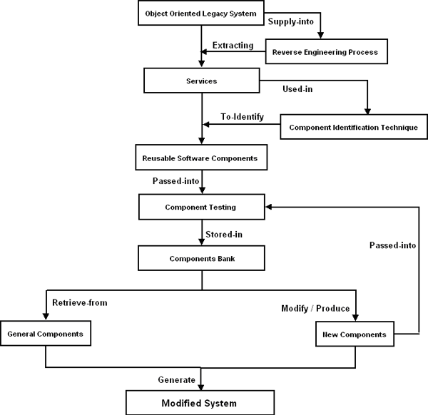
CBD96 [Dodd99]The CBD96 method adopts a business component identification method that groups closely related objects. This method does not factor in the concept of reusable system components and suffers from dependency on the intuitions and experiences of individual developers and mandatory consideration of the entire domain knowledge. Cheesman and Daniels [Daniels01]The method proposed by Cheesman and Daniels is named as Advisor method, which is the extended version of CBD96 method. It includes a method to identify components using use cases and business type models. In this method, the authors’ uses inter-class relationship as the main circumstance for identifying components. The core class treats as the center of each clustering, and responsibility derived from use cases is used to guide the process. Lee et, al [Lee99]“COMO: A UML-Based Component Development Methodology” is a component identification method proposed by Lee et, al. It extends Unified Modeling Language (UML) and Rational’s Unified process with semantics related to component development. This method measures the inter-class relationships in terms of create, retrieve, update and delete (CRUD), and uses a clustering algorithm of shifting rows and columns which is also found in information engineering. In addition, it uses dynamic coupling metric between objects to measure the potential number of messages exchanged. It suggests basic techniques to resolve conflicts in clustering. However, this method only focuses on the data dependency between the classes. S.D.Kim and S.H.Chang [Kim04]The method, “A Systematic Method to Identify Software Components” proposed by Kim and Chang is basically focuses on high cohesion and low coupling while identifying the reusable components. This approach makes use of clustering algorithms, metrics, decision rules and a set of heuristics. This method assumes that an object-oriented model for a target domain is available, including use case model, object model and dynamic model, by using these artifacts and transforms them into components in a seamless way. This method is only concentrate on use case dependency not on focuses on structural relationships among the classes and their message call information. 3 COMPONENT ORIENTED REVERSE ENGINEERINGWe propose a process model to reengineer an object-oriented legacy system into a component-based system, named as Component Oriented Reverse Engineering (CORE), this aims to identify and develop reusable software components. Looking at the reverse engineering process with software component’s point of view shows that there is very promising scope to extract services from the object oriented legacy system. Once we able to extract services from legacy systems, we can convert these services into reusable software components based on component identification techniques. Since the components are platform independent and language interoperable, they may become strong candidates for reuse. These components are not originally designed according to the modern component paradigm, so they may not be directly suitable for component-oriented programming. Here, the challenge is to identify the components in such a way that the resulting components have object orientation. A component identified from legacy system may not be compatible with other components at first hand; to achieve this component wrapping would be required. Some GUI features can be added in identified components. Due to this reason, wrapping of components is necessary to eliminate the possible architectural mismatches. The software component creation activity may add the extra effort in the software reverse engineering but finally reduce the time and cost of the forward engineering and other software developments. We can store these components in Component Bank after component testing phase so that any software developer can reuse these components during new development. “Component Oriented Reverse Engineering (CORE) is a process to use reverse engineering methodology to expose components from the object oriented legacy system, to use repository to store and manage the tested components, then restructures the new system and finally integrate the new system with reusable components and newly produced components by forward engineering”.
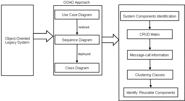
Fig-1: Component Oriented Reverse Engineering (CORE) Process Model Component Identification TechniqueThe reusability of the software component is most popular way to enhance the productivity and improve the quality and reliability of new software systems by reducing the development cost. Due to this reason, it is very important to identify independent components having low dependency and high reusability. However, the existing component identification techniques do not provide the concrete guideline for component based development. Therefore, we propose a systematic approach to identify reusable component from object oriented legacy system through OOAD models namely use case, communication diagram and class diagrams. Accordingly, the component identification technique may identify reusable components more effectively based on facility of CRUD matrix, class clustering.
Fig-2: Component Identification Approach To break down the system into components, the software developer needs an understanding of how the object oriented legacy system is built. This task can be accomplished by selecting certain points within the system and expanding the boundaries of those points until all related system elements are included within the boundaries. Here, by using the reverse engineering approach, we are able to extract services points of legacy system and further restructure this system through OOAD approaches. OOAD approach is oriented to the tasks and the relevant objects, including their interactions, generalization and composition are used to represent the related terms in domain concept model [Larman05]. Here, we represent the OOAD approach from three points of view, i.e. functional, behavioral and structural corresponding to use case, sequence diagram and class diagram. We can extract the structural relationships among the objects from class diagram; the sequence diagram is used to obtain the object usages, which represent the CRUD Matrix and some additional object information can be specified by the help of use case when ever it needs. System Component Identification:The existing methods for identifying components do not offer any concrete guidelines and expose components by grouping mechanism. We group the use cases into a use case when they share in aggregation relationships. The use-cases having the similar functionalities are grouped together. Finally, by considering the relationships between the classes are utilized to identify the system components [Sook05]. CRUD Matrix:CRUD analysis suggests that which object type is Created, Deleted, Read, and Updated during some scenarios [Sook05]. Each scenario is going to be detailed in UML with one (or more) of the dynamic design drawings such as sequence diagram as well as structure diagram showing the relationships between the classes and the class attributes and operations. Message-call Information:After the construction of CRUD (Create or Read or Update or Delete) matrix, we propose Message-call Information to represent both structural relationships between the objects and use of CRUD matrix. Here, we define a message-call between the classes inside the system components using sequence diagram to cluster the related classes. Clustering Classes:We identify the reusable components by clustering the classes according to their dependency characteristics by assigning different weight values of corresponding dependency relationships. According to the domain experts, the value lies between 0 to 1. Based on this observation, the structural relationship strength is as below: 1 > Aggregation > Generalization > Association > Dependency > 0 [Kim05]. There are some rules provided for clustering the classes:
4 CASE STUDY AND EVALUATIONIn order to validate the proposed approach, a case study has been performed on Library Management System (LMS). The requirement scenario for this case study is taken from the object oriented legacy system, named Library Management. Phases of proposed approach for case study: The steps through which the case study has been done are as follows:
Analysis phase of legacy system through Reverse Engineering: By using the reverse engineering tool, named Rational Rose, we analyze the services from the legacy system. It means that the legacy code is used as input to this tool and generating the class diagram through reverse engineering. By using this class diagram as shown in fig-3, we are able to restructure our legacy system if needed.
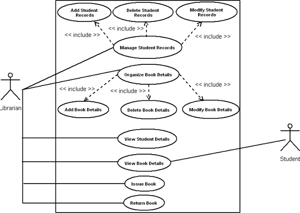
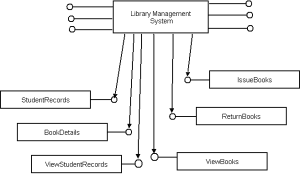
Fig-3: Legacy System Restructuring the legacy system through OOAD approach: In this phase, we are considering above class diagram for requirement analysis to build the component based system. Here, we have identified following use cases to find out the functional dependencies, sequence diagram for behavioral relationship and finally design class diagram to predict structural relationships. The identified use cases are: Manage Student Records, Organize Book Details, View Book Details, View Student Records, Issue Books, and Return Books. The use case diagram and their description are shown below:
Fig-4: Use Case Diagram for LMS
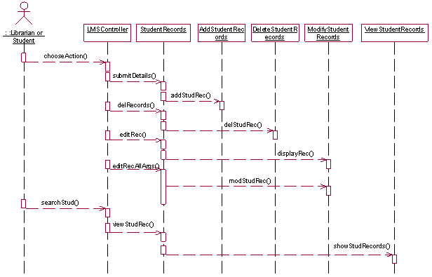
Fig-5: Partial Sequence Diagram for LMS
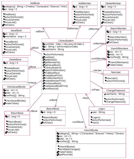
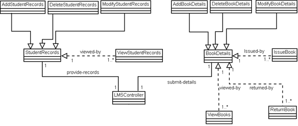
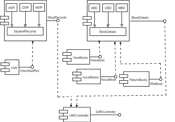
Fig 6: Design Class Diagram Applying component identification phase: This phase focused on system component identification, CRUD matrix, message-call information, component architecture and finally component interfaces. System Component Identification:
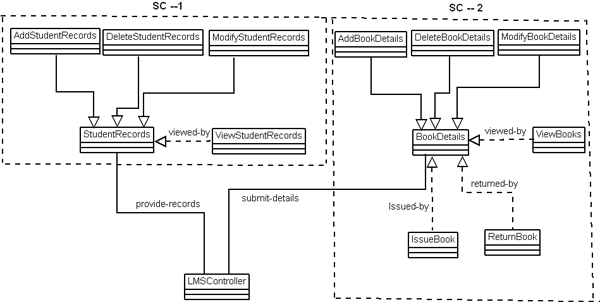
Fig 7: System Component Identification The identified system components and their classes are shown below: Table-1: system components and their classes
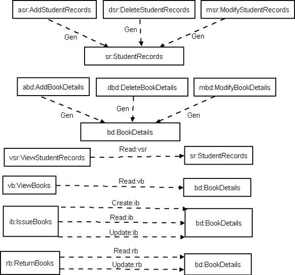
CRUD MATRIX: Table-2: CRUD Matrix
Message-call Information:
Fig 8: Message call Information between the Classes Identified Reusable Components: According to the Message-call Information Graph and Clustering Classes approaches, we identified the following reusable components: StudentRecords, BookDetails, IssueBooks, ReturnBooks, ViewBooks and ViewStudentRecords. System Component Architecture:
Fig 9: System Component Architecture
Fig 10: Component Interface Diagram # ASR – AddStudentRecords # DSR – DeleteStudentRecords Implementation of reusable components: There are various component technologies (EJB, CORBA, COM+, .Net etc.) in which we can implement our components. Among these, we have developed our components in most recent component technology; .Net. We use visual studio .Net 2005 for the implementation of components [Brand02]. Component Testing: Component-based development and software reuse places new demands on software testing and quality assurance. Testing a software component is basically done to resolve the following issues:
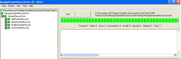
Here, we use NUnit as a testing framework for all .Net languages. NUnit provides a class library which includes some classes and methods to help us to write test scripts. NUnit provides graphical user interface application to execute all the test scripts and show the result as a success/failure report. NUnit does not create any test scripts by itself but NUnit allows us to use its tools and classes to make the unit testing easier [Kim05].
Fig-11: Component Testing using NUnit Framework 5 COMPONENT REGISTERING & COMPARISION To add the serviced components in assembly to a COM+ application, we need to register that assembly with COM+. To register the component manually, use the RegSvcs.exe command-line utility. RegSvcs accepts as a parameter the name of the file containing our assembly's metadata.
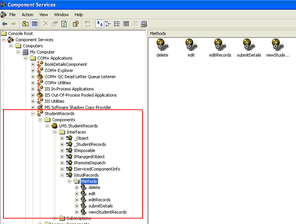
The bottom of the AssemblyInfo.cs file should look similar to this: [assembly: AssemblyKeyFile(@"C:\Component Test\StudentRecords.snk")] Here, by using the RegSvcs.exe command-line utility we can register our components. C:\Component Test>regsvcs StudentRecords.dll Finally, we can view our registered component by using component services.
Fig-12: Component Services Result Comparison:The table 3 shows the results of comparison between our approach and the existing methods in terms of the different ways for component identification techniques. Hence, the results obtained by using our approaches matched what our intuition indicated. Table-3: Result Comparison
S -- Supports p ---partially supports N---Not Used 6 CONCLUSION AND FUTURE WORKWe have proposed a model named Component Oriented Reverse Engineering (CORE) for identifying and creating reusable software component. It encompasses reverse engineering methodology to expose components from the object oriented legacy system. It makes use of repository to store and manage the tested components and restructures the new system that finally integrates the new system with the reusable components. The reusability of the software component is most popular way to enhance the productivity and improve the quality and reliability of the new software systems by reducing the development costs. Due to these reasons, it is very important to identify independent components having low coupling and high cohesion. We have also proposed a systematic approach to identify reusable component from object oriented legacy system through OOAD models namely use case, communication diagram and class diagrams. Accordingly, the component identification technique may identify reusable components more effectively based on facility of CRUD matrix, class clustering. We have validated our approach by using a case-study named Library Management System and also test our components for reusability and the result shows that our approach supports all the 5 major functionalities illustrated in table 3. In future, if we can automate this proposed methodology by an automatic tool then it could be more effective and less time consuming. REFERENCES[Ben94].K. Bennett, “Legacy Systems: coping with success”, IEEE Software, 1994. [Kim06] H.K.Kim, Y.K.Chung, “Transforming a Legacy System into Components”, Springer-Verlag Berlin Heidelberg, 2006. [lai07] S. Mahmood, R.Lai and Y.S. Kim, “Survey of Component-based software development”, IET Softw, Vol. 1, No. 2, April 2007. [Woods98] R. Kazman, S.G.Woods, S.J.Carrii,"Requirements for Integrating Software Architecture and Reengineering Models: CORUM II", IEEE, 1998 [Abowd97] Abowd G, Goel A, Jerding D.F., McCracken M., Moore M., Murdock J.W., Potts C., Rugaber S. Wills L., “MORALE. Mission Oriented Architectural Legacy Evolution” International Conference on Software Maintenance, ITALY, October, 1997, [Dodd99] John Dodd: “Identifying & Scoping CBD96 Components”, Texas Instruments Inc., 1999. [Daniels01] J. Cheesman and J. Daniels, UML Components: A Simple Process for Specifying Component-Based Software, Addison Wesley, 2001. [Lee99] S.D.Lee, Y.J.Yang, E.S.Cho, S.D.Kim, S.Y.Rhew, “COMO: A UML- Based Component Development Methodology”, IEEE, 1999. [Kim04] S.D.Kim, S.H.Chang, “A Systematic Method to Identify Software Components”, Proceedings of the 11th Asia-Pacific Software Engineering Conference (APSEC’04), IEEE Computer Society. [Martin] Ludger Martin, “Visual Component Integration and Regression Test”, Darmstadt University of Technology, Dept. of Computer Science, Germany [Wu03] Ye Wu, Mei-Hwa Chen, and Jeff Offutt, “UML-Based Integration Testing for Component-Based Software”, George Mason University, State University of New York Springer-Verlag Berlin Heidelberg 2003 [Larman05] Craig Larman, “Applying UML and Pattens”, 3rd Edition, Copyright © 2005 by Pearson Education, Inc. [Sook05] M. Sook and E.S. Cho, “A Component Identification Technique from Object-Oriented Model”, Springer-Verlag Berlin Heidelberg, 2005. [Brand02] Daniel Brandon, “CRUD Matrices for detailed object oriented design”, Copyright © 2002 CCSC: Southeastern Conference. [Negal05] C. Nagel, B.Evjen, J.Glynn, M.Skinner, K.Watson, A.Jones, “Professional C# 2005”, Copyright © 2006 by Wiley Dreamtech India (p) Ltd. [Kim05] Haeng-Kon Kim and Oh-Hyun Kwon, “SCTE: Software Component Testing Environments”, Copyright ©Springer-V.B Heidelberg, 2005 [nunit] www.nunit.org [Code04] http://www.codeproject.com/csharp/simplecompluscache.asp, April 2004. About the authors
Cite this article as follows: Mr S.K.Mishra, Dr.D.S.Kushwaha, Prof.A.K.Misra: “Creating Reusable Software Component from Object-Oriented Legacy System through Reverse Engineering”, in Journal of Object Technology, Jan-Feb 2009, pp.133-152 http://www.jot.fm/issues/issue_2009_07article3/ |
|||||||||||||||||||||||||||||||||||||||||||||||||||||||||||||||||||||||||||||||||||||||||||||||||||||||||||||||||||||||||||||||||||||||||||||||||||||