Generic Red-Black Tree and its C# ImplementationDr. Richard Wiener, Editor-in-Chief, JOT, Associate Professor
of Computer |
COLUMN PDF Version |
The focus of this installment of the Educator’s Corner is on tree construction – red-black trees. Some of the material for this column is taken from Chapter 13 of the forthcoming book “Modern Software Development Using C#/.NET” by Richard Wiener. This book will be published by Thomson, Course Technology in the Fall, 2005.
A fascinating and important balanced binary search tree is the red-black tree. Rudolf Bayer invented this important tree structure in 1972, about 10 years after the introduction of AVL trees. He is also credited with the invention of the B-tree, a structure used extensively in database systems. Bayer referred to his red-black trees as “symmetric binary B-trees.”
Red-black trees, as they are now known, like AVL trees, are “self-balancing”. Whenever a new object is inserted or deleted, the resulting tree continues to satisfy the conditions required to be a red-black tree. The computational complexity for insertion or deletion can be shown to be O(log2n), similar to an AVL tree.
Red black trees are important in practice. They are used as the basis for Java’s implementation of its standard SortedSet collection class. There is no comparable collection in the C# standard collections so a C# implementation of red-black trees might be useful.
The rules that define a red-black tree are interesting because they are less constrained than the rather strict rules associated with an AVL tree. Each node is assigned a color of red or black. This can be accomplished using a field of type bool in class Node (true if the node is red and false if it is black).
The formal rules that define a red-black binary search tree are the following:
- Every node is colored either red or black.
- The root node is always black.
- Every external node (null child of a leaf node) is black.
- If a node is red, both of its children are black.
- Every path from the root to an external node contains the same number of black nodes.
It is rule 5 that leads to a balanced tree structure. Since red nodes may not have any red children, if the black height from root to every leaf node is the same, this implies that any two paths from root to leaf can differ only by a factor of two. Using a relatively simple proof of mathematical induction, Kenneth Berman and Jerome Paul show on page 659 of their book, Algorithms: Sequential, Parallel, and Distributed, Thomson, Course Technology, 2005, that the relationship between the maximum depth of a red-black tree and the number of internal nodes is, depth = 2 log2(n + 1) where n is the number of internal nodes.
Let us consider some examples of red-black trees in Figure 1.
The first red-black tree has a black depth of 2 from the root to every leaf node. The second red-black tree has a black depth of 3 from the root to every leaf node. Each of these trees is generated by a search tree GUI application (to be the subject of a future column).


Figure 1 – Two Examples of Red-Black Trees
The algorithms for insertion and deletion involve node rotations as well as node re-coloring.
The algorithms with examples of insertion and deletion are presented first. Following this a complete implementation of class RedBlackTree is presented that includes all the implementation details for insertion and deletion.
Mechanism for insertion into a red-black tree
Perform an ordinary binary search tree insertion into the red-black tree. If the path from root to the new leaf node that contains the information being inserted passes through a node that contains two red children, re-color these nodes black and re-color the node with the two previously red children black, assuming that it is not the root node (if it is, leave the node black since the root node of a red-black tree must be black).
Color the new leaf node just inserted red.
If the steps above lead to a succession of two red nodes in moving from the root down the tree, a rotational correction is needed. There are four possible rotations that are possible. Two of these are illustrated in Figures 2(a), (b). The other two are mirror images.

Left rotate on N2 and color N1 red and N2 black.

Figure 2a – Rotational and Recolor Correction

Figure 2b – Rotational and Recolor Correction
Right-rotate on N2 then left-rotate on N3 and perform appropriate re-coloring (details to be provided later).
Consider the sequence of insertions shown in Figure 3. After each insertion, the new red-black tree is displayed.
When node 50 is added, the search path passes through node 200 that contains two red nodes. This causes these nodes to be re-colored black.
After node 250 is added, the insertion of 275 causes the rotation and re-coloring shown in Figure 3d. After inserting 280, the final tree is shown in Figure 3e. No rotations are required.

Figure 3a – Initial Red-Black Tree

Figure 3b – Red-Black Tree After Inserting 50

Figure 3c – Red-Black Tree After Inserting 250

Figure 3d – Red-Black Tree After Inserting 275

Figure 3e – Red-Black Tree After Inserting 280
Mechanism for deletion from a red-black tree
The algorithm for deletion is more complex than the algorithm for insertion. There are seven special cases to consider.
The first step is to perform an ordinary binary search tree deletion. In the case where the node being deleted has two children, we copy the value but not the color of the in-order successor. Then we delete the in-order successor, a node that can have at most one child.
If the node being deleted is colored red, no further corrections are needed. If the deleted node is black and it has a red right child, the red right child is re-colored to black and this serves to restore the tree to red-black status.
When the node being deleted node is black and it has no right child or a black right child, the following table indicates which of the seven cases needs to be utilized.
This table is an adaptation of Figure 21.8 in Berman and Paul’s book cited above. The asterisk indicates any color. R indicates red and B indicates black.
| Case | 1 | 2a | 2b | 3 | 4 | 3' | 4' |
| Parent | B | B | R | * | * | * | * |
Sibling |
R | B | B | B | B | B | B |
| Sibling (LC) | B | B | B | R | * | B | R |
| Sibling (RC) | B | B | B | B | R | R | * |
From the starting state, any of the states can be reached. From state 1, a transition to either state 2b, state 3 or 4 occurs. When in state 2a, a transition back to state 2a, 2b, 3 or 4 occurs. When in state 3, a transition to state 4 occurs. When in state 3’, a transition to state 4’ occurs.
We consider states 1, 2a, 2b, 3 and 4 below. States 3’ and 4’ are mirror images of states 3 and 4. In each diagram, Current Node represents the right child of the actual node deleted (null in many cases). The R or B in parentheses indicate the node color.
State1
Change color of Parent and Sibling and left rotate on Parent. Make transition to case 2b, 3 or 4.
State 2a
(Same diagram as state 1)
Change color of Sibling to red and then redefine Current Node as Parent. Compute new sibling and parent. Make transition back to state 2a or to case 2b, 3 or 4. Often Current Node gets moved up the tree in state 2a as transitions occur from 2a back to 2a.
State 2b
(Same diagram as state 1)
Change color of sibling to red and end.
State 3
(Same diagram as state 1)
Change color of sibling to red and its left child to black and then right rotate on sibling. Make transition to case 4.
State 4
(Same diagram as state1)
Change color of sibling’s right child to black, make parent black, color sibling the color of parent and then left rotate on parent and end.
Several examples are presented that demonstrate some of the cases defined above.
Consider the tree shown below. We wish to delete node 250. The right child of 250 is null so the Current Node is null. Its parent is 225 (after the deletion when the left child of 350 becomes 225) and its sibling is null. Since its parent is colored red, the system goes from the start state to state 2b.

This leads to the result shown below in which the color of 225 is changed to black.

Consider the deletion of 250 from the following tree:

The table of states given above suggests that from the start state a transition to state 3’ occurs. The Current Node is null, its parent is 247, its sibling is 225 and its sibling’s right child is red. These are the conditions needed for state 3’. After the node re-coloring indicated under state 3’ above, a left rotate is done on the sibling node 225. A transition to state 4’ occurs. After more re-coloring, a right rotate on node 247 brings red node 230 to the left of 350. The tree resulting from states 3 ’ and 4’ is shown below.

Consider the deletion of node 77 from the following red-black tree:

From the start state a transition is made to state 2a since the parent, node 182, is black, the sibling, 190 is black and the children of the sibling (null) are black.
From state 2a a transition is made to state 3 and then state 4. The final tree after these three states is shown below.
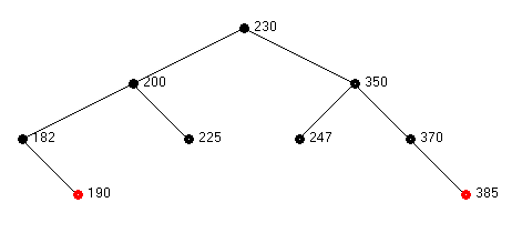
Unless one studies these transitions carefully, it simply looks like magic.
As the final example consider the deletion of node 225 from the following red-black tree:

From the start state a transition to state 1 occurs. This is because
the sibling, node 370, is red and the parent, node 247 is black.
Two Alternative Designs of Red-Black Trees
The algorithm for insertion requires that the ancestors (parent, grand parent, great grand parent) of the inserted node be available. The implementation of deletion requires that the parent, sibling and grandparent nodes be available from the node being deleted. This leads to an important implementation question: should each node of a red-black tree have a link “pointing” to its parent (the root would link to a parent of null)? The alternative is to stay with the same structure as used in the implementation of the binary search tree and AVL tree in which each node is linked to its two children and not to its parent. The tradeoff is replacing more complexity in the basic operations of insertion and deletion with easier implementations of the various rotational and re-coloring “corrections” related to insertion and deletion.
The decision is to use the more complex node structure in which each node contains a link to its parent node since this leads to the most efficient implementation of the red-black tree, particularly for deletion. An implementation that does not use links from child to parent requires a field, stack, and recursive ConstructStack method whose purpose is to determine the nodes in the path from root to any specified node. Because of the need to frequently invoke this method, the implementation for deletion is 100 times slower than an AVL tree with the same node values. This is unacceptable and leads to the focus on the version that contains links from child to parent nodes.
Comparing performance of binary search trees
The results of a simulation that compares the execution time required for inserting a sequence of values and later removing them from an unbalanced binary search tree, an AVL tree and a Red-Black tree are presented first. The two types of red-black tree implementations, with and without links to parent nodes, are included in the table even though only the implementation of the version with links to parent nodes will be presented. An ascending sequence of integers of size shown is used to construct each tree. Then all the values that were used to construct the tree are used in a sequence of deletions.
| Tree Type | Number Nodes | Time for Insertion | Time for Deletion | ACE Value of Tree |
| Binary Search Tree | 10,000 | 34.48 seconds | 5000.5 | |
| Red-Black Tree (No links to parent nodes) | 10,000 | 0.0312 seconds | 2.844 seconds | 12.88 |
| Red-Black Tree (Links from child to parent nodes) | 10,000 | 0.0156 seconds | 0.0156 seconds | 12.88 |
| AVL Tree | 10,000 | 0.0156 seconds | 0.0156 seconds | 12.36 |
| Red-Black Tree (Links from child to parent nodes) | 1,000,000 | 3.609 | 1.0625 | 19.33 |
| AVL Tree | 1,000,000 | 2.406 seconds | 1.031 | 18.95 |
It is clear from the table above that the performance of the red-black tree with each node linking to its parent is superior to the red-black tree without such links to parent nodes and comparable to the performance of the AVL tree.
Implementation of class Node with upward links
The details of class Node are presented in Listing 1. It is a nested class (similar to Java’s static inner class) in a generic class with parameter T (as seen later) so it does not require its own generic parameter.

Tree rotation with upward links to parent nodes
The methods LeftRotate and RightRotate must take the parent link into account. Method LeftRotate is presented in Listing 2. Method RightRotate is the symmetrical opposite and not presented. The reference parameter capability of C# (ref parameter) is utilized in the two rotation methods. This allows explicit linking between the tree structure unaffected by the rotation and the new node that is passed back through the reference parameter.
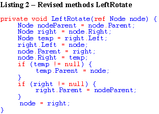
After setting the right child of ref variable node to temp, the parent of temp is set to node (if temp is not null). This reflects the new parent of temp after the rotation is completed. The parent of right is set to nodeParent, a local variable that is immediately assigned as the first line in the method. This reflects the upward connection between the node being passed back (right) and its parent (not affected by the rotation). These two assignments using Parent ensure that the two links that are modified by the rotation are linked in both directions.
Implementation of insertion
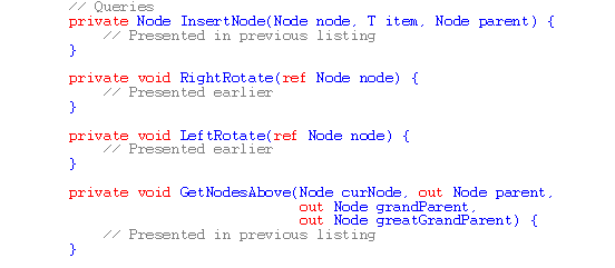
The public method Add and its private support methods InsertNode, GetNodesAbove and FixTreeAfterInsertion implement the red-black algorithm for insertion.
These methods are presented in Listing 3.

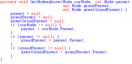


The recursive InsertNode contains a parameter, parent, which allows node at one level of recursion to be passed as parent to the next lower level of recursion.
The support method GetNodesAbove use the out parameter facility of C# to return relevant nodes above the current node (curNode). This can be easily accomplished because of the upward links in the node structure.
The important support method FixTreeAfterInsertion with four nodes as input implements the details of the red-black insertion algorithm as outlined and illustrated above. Care has been taken to use descriptive local variable and parameter names to make it easier for the code to be self-documenting
Implementation of deletion
The implementation of deletion is more complex than the implementation of insertion. This reflects the additional complexity of the algorithm for deletion which as you have seen earlier involves seven special cases and transitions from some of the cases to other cases. The remaining portion of class RedBlack that includes all the support for deletion is presented in Listing 4.
The generic class uses a constrained generic parameter T where T implements the IComparable interface.

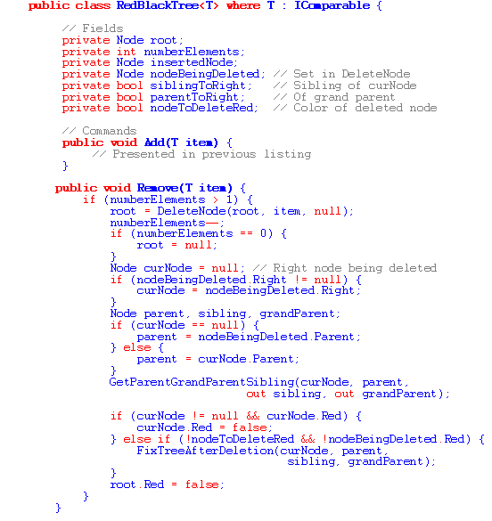


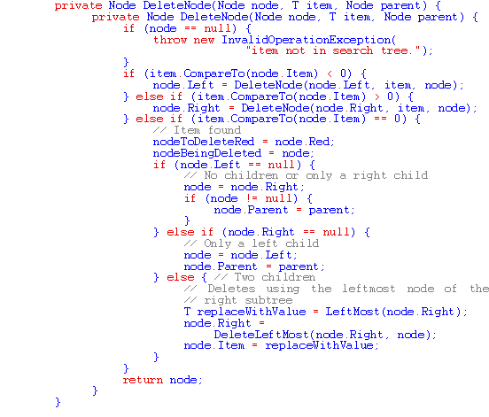

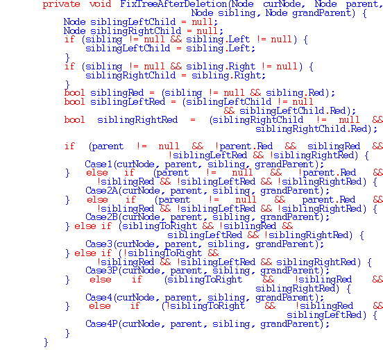
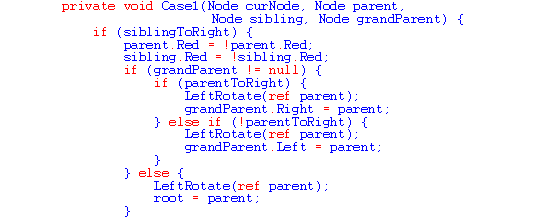

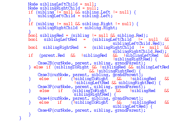
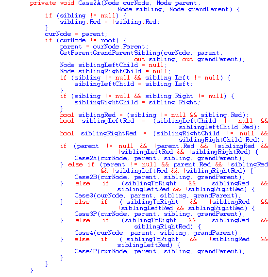


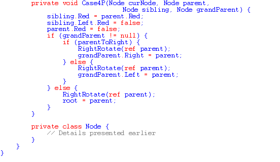
Care was again taken in choosing variable and parameter names so that the code would be self-documenting. The complexity of the code reflects the complexity of the algorithm for deletion.
C#’s requirement that ref or out parameters must be explicitly tagged when invoking a method is desirable. It makes the semantics of the method invocation clear without requiring the programmer to refer back to the method signature. There are many examples of such method invocations in Listing 4.
In a future column, a GUI application that renders a graphical depiction of search trees as values are inserted in or deleted from ordinary binary search trees, AVL trees and red-black trees is presented. This GUI application was used as a test-bed while developing the code presented in this paper.

