AbstractA model is built when the complexity of something we are building exceeds our ability to internalize it. Most commercial software products fit that definition. A number of modeling languages have emerged to support software development methods that are guided mainly by models of the product being built. In this issue of Strategic Software Engineering I will consider some of these languages, but more importantly, I will consider how they can be made more effective by integrating models from several languages. 1 INTRODUCTIONI was having a discussion the other day with some automotive domain people. They were considering how to overcome the problems of building the amount of software needed in a vehicle. Software is anticipated to go from being 4.5% of the value of a car to some 13% in the next few years [Mercer 01]. One of the problems they are facing is the difficulty of managing software development down the supply chain and across the functional divisions within the company.The automotive industry has a very hierarchical supplier structure. Tier N suppliers aggregate assets from Tier N+1 suppliers. The depth of the hierarchy imposes an additional communication burden. Automotive engineers have formalisms for communicating with suppliers about hard goods but less so about software. Specifications passed down to suppliers need to be sufficiently expressive to ensure accurate communication. There are increasing numbers of interactions between subsystems of the vehicle. The braking system and the navigation system talk to keep the vehicle on track. Many other interactions occur and these cut across organizational boundaries in the enterprise. Devoting separate networks to subsystems does not solve the problem since the subsystems must interact at some level. Managing the interactions calls for an explicit model of the interactions. Automotive engineers have built models and various types of prototypes for many years and they have mature tools such as Simulink[Math 08]. Model-driven development (MDD) of software is a more recent phenomenon but it is maturing at a rapid rate. I believe that many of the problems faced in automotive software can be addressed by adequate modeling and model management. In this issue of Strategic Software Engineering I will explore a particular perspective on MDD. A model is an abstraction of some entity. A model is created by eliminating some details and exposing properties of the entity that are of interest so that those properties can be analyzed. Multiple models may be created for an entity, each focusing on a different property. For example, an architectural model of a software-intensive product abstracts away the details of implementation. What remains is the fundamental structure of the product. We can deduce many things from this structure including the performance of specific features and the maintainability of the system as a whole. Other models, such as a requirements model, will be built for this same product. Each model is based on a specific viewpoint, such as that of a requirements analyst or a tester. Each of the models presents a particular view from that viewpoint. For example, the tester might only be interested in the product requirements for input and output to facilitate the development of system test cases. Each modeling language defines several diagram types. A diagram type provides a specific view on the entity. For the types of models we will be discussing, a model is composed of multiple diagrams, each of which is an instance of a diagram type. For example, a single design model will usually have multiple diagrams in which types are defined, several diagrams of the stateful behavior of the objects in the system and several different diagrams mapping the design to hardware. There must be some well-defined mapping between the model and reality, which in our world means between the model and compilable source code. Models may be interpreted by humans who then write the code or the model interpretation may rest in patterns that are automatically applied to generate code. The ability to map the model to different "realities", such as different platforms, is what makes modeling so powerful. My primary interest for this column is modeling as a verb, but I will also briefly address modeling as an adjective. I am going to first describe relevant portions of three modeling languages, each of which I have discussed before and each of which is too large to fully cover here. Then I will describe an approach that integrates the languages into an effective modeling environment. 2 THREE LANGUAGESImproved techniques such as metamodels and profiles have led to a large number of modeling languages being defined in recent years. Technologies such as that provided by the Topcased project generate context-sensitive editors from a basic grammar [Topcased 08]. Each has its advantages and disadvantages. Each typically is defined for a specific purpose. Unfortunately, sooner or later, someone uses the language for a purpose other than the intended. The mismatch between purpose and practice oftens reduces the effectiveness of the models built with the language and leads someone to question the quality of the language. Usually the ineffectiveness is simply attributed to defects in the language rather than the mis-user. The three languages described in this section are each intended for a specific purpose. Yet, for each there are examples where the modeling language was used in ways not anticipated. Each of these languages is used by a community, has proven effective for its intended purpose, and is widely used. SysMLThe System Modeling Language (SysML) was developed by the Object Management Group (OMG) in cooperation with the International Council on Systems Engineering (INCOSE) to support the systems engineering process [SysML 08]. The language was developed as a profile of UML with extensions. It is currently being refined into a second version. The systems engineer begins the definition of a system by considering the total set of requirements for the system. This encompasses both hardware and software. The engineer captures the system requirements using a requirements diagram, like the one shown in Figure 1. The systems engineer then allocates those requirements to hardware and software using a block diagram, illustrated in Figure 2. Finally the systems engineer develops a use case diagram, shown in Figure 3, to elaborate the software requirements.
Figure 1 SysML Requirements Diagram
Figure 2 SysML block diagram
Figure 3 Use case diagram AADLThe Architecture Analysis and Design Language (AADL) has been developed as a standard of the Society for Automotive Engineers (SAE) [AADL 08]. As the name implies the language is intended as an architecture description language. The language is extensible and facilitates domain specific definitions. AADL has text, graphic, and XML-based representations. Figure 4 shows some basic symbols that occur in a graphical AADL model. What is not shown in the graphical model are the properties that are the basis for analysis algorithms. Shown in Table 1 is the text representation of the specification of a thread from the CurrencyAcceptor system in the vending machine example. The properties section of the implementation definition defines a number of properties that influence the execution. These property definitions are a key factor in using the architectural model for analysis. The "DispatchProtocol" property describes the manner in which the thread will operate and send out events. The connectors in the figure show flows of events within the system. These flows are the basis for the performance analysis of architectures.
Figure 4 AADL System diagram
Table 1 AADL Text Example
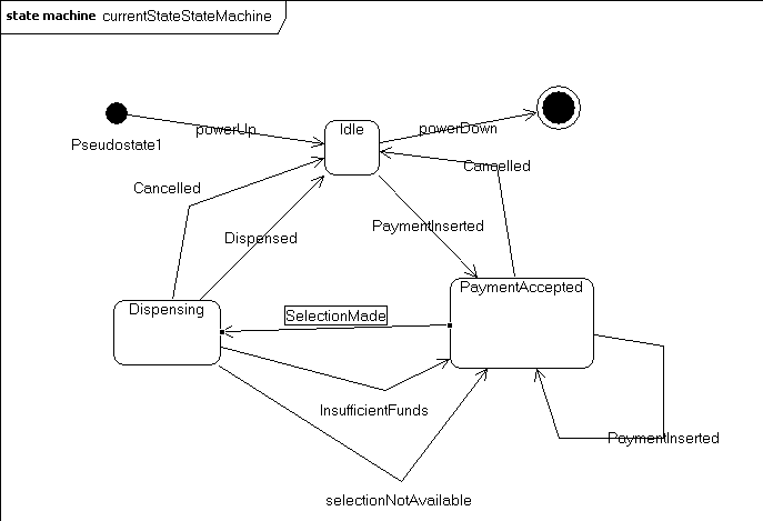
UMLThe Unified Modeling Language (UML) was developed as a standard by the Object Management Group (OMG) [UML 08]. The language was intended as a design language, but it has been used to model at all levels of software development including architecture. In fact some authors even make the mistake of saying that UML stands for Universal Modeling Language instead of Unified Modeling Language. OMG has repeatedly modified UML in this more general direction. UML is an object-oriented modeling language and as such is most expressive when defining object types (classes), instantiating concrete objects, and describing the interactions of objects. Objects can represent concrete or conceptual entities and the relationships supported by UML are sufficiently general to model knowledge in a domain. UML also provides diagram types, sequence and activity diagrams, to model the interaction and behavior of the objects. Portions of a UML class diagram, see Figure 5, and a state diagram, see Figure 7, are shown just as brief reminders of the structure of these diagrams. The class diagram provides a static, definitional, view of concepts and their relationships. The state diagram specifies the sequence of events that direct the execution. Figure 6 shows a sequence diagram that is used to illustrate a sequence of interactions.
Figure 5 UML class diagram
Figure 6 User interface
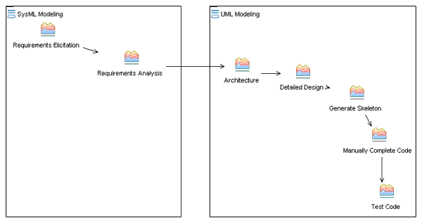
Figure 7 State diagram for vending machine SummaryThese languages share a number of characteristics but differ in significant ways. SysML is most expressive when providing high-level, system-wide models. AADL is most expressive when used to define structural and behavioral aspects of a system at the architectural level of detail. UML is most expressive when illustrating design concep ts. The most effective model-driven development process will be one that uses each language to its best advantage. This is made feasible by yet another class of language: transformation languages. QVT-based languages (Query-View-Transformation) such as ATL allow a development organization to pass models from one activity to another along a process thread, transforming the model from one language to another as needed [QVT 08]. 3 COMPREHENSIVE MODEL DRIVEN PROCESSThe modeling languages described in the previous example provide capabilities that can be used in a variety of ways in software development. In this section I will describe two different arrangements of development activities that use these languages to model the system under development. SimpleThe simple software development example involves the use of SysML and UML for the phases shown in the activity diagram in Figure 8. (The simplest approach would use only UML but I think that the value of SysML for defining the different platforms for which even software-only products are destined is worth the effort of using two languages.) In this process system development begins with requirements elicitation and analysis using the SysML requirements diagram. The requirements are allocated to hardware and software blocks and the software development process attacks the software requirements. Then an architecture and detailed design are defined and finally code is developed. The requirements model seeks to capture the initial information provided by stakeholders and then to transform that information into a more actionable form. The SysML requirements diagram is used for the elicitation of requirements for our system. The requirements are analyzed to produce a set of use cases which are captured in a use case diagram. During the analysis activity linkages are established via the relationships to ensure traceability from later stages back to the earlier stages. The main work is seen in the UML swimlane of the activity diagram. The use cases from the previous phase are input to the architecture definition activity. The architecture representation will be simple, since UML does not have native elements for architecture description. The Detailed Design will be quite complete since this is the area in which UML excels. From the design a program skeleton will be generated but much code will then be written by hand and tested manually.
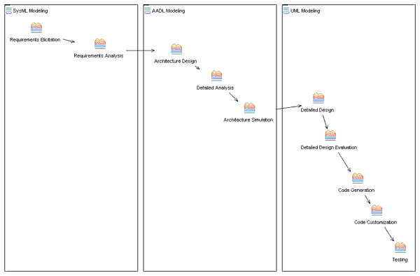
Figure 8 The Simple Modeling Process ElaboratedThe Elaborated development process adds steps to provide additional analysis activities at the architecture level, see Figure 9. In this thread the UML modeling is prefaced by a deeper level of behavior modeling using AADL. There are a number of analysis algorithms and tools that work on AADL models. The OSATE toolkit developed at the Software Engineering Institute (SEI) provides a basic set of analyses for AADL models [AADL 08]. These analyses include semantic checks, flow latency analysis, and others. Since the OSATE toolkit are Eclipse plugins, additional plugins have been developed by others that interact with the OSATE plugins to perform a variety of analyses. A primary feature that supports these activities is the ability to create user-defined properties. An analysis can be defined and the appropriate properties added to the model. Properties such as integrity and security are quantified in a variety of schemes to support the analysis algorithms. The addition of these properties and constraints in the architecture model provides additional information that changes the nature of the UML model. This is reflected in the more complete code generation. Code is customized rather than needing "from scratch" authoring. Testing is still needed but many of the defects found in testing in the first process will now be found during the architecture analysis earlier in the life cycle. This high-level process addresses many concerns. The architecture design process includes designing a failure management architecture and provides a means of addressing a number of non-functional attributes such as security and reliability. Using a language such as AADL also provides for accurate simulation of executions of finished products using the architectural model. This provides early warning of difficulties.
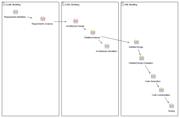
Figure 9 Elaborated Modeling Process Variation on a themeDeveloping an architectural model that has sufficient detail to support complete code generation is a resource intensive process. In this process variation, the simulation phase produces information that is used by humans to improve the UML model, see Figure 10. This results in less effort for a one-off product development effort. In a product line organization the process in Figure 9 is less effort since the transformation must be carried out multiple times and the effort required to automat is paid back many times over. In this variation, instead of a QVT transform from the AADL model to the UML model, the information is carried by a human. The model can probably be developed more quickly this way but it can not easily be modified without the human being in the loop. In the previous process the architecture model will take longer to produce but modifications to products can be handled much more quickly.
Figure 10 Detailed Analysis and Human Intervention 4 NON-FUNCTIONAL ATTRIBUTESThe non-functional qualities of a system have become of more interest particularly from a management perspective. Here are a couple of attributes that are important in large scale development. TraceabilityAssets created during development are handed off many times from one developer to another or from one team to another. It is often necessary to be able to verify that what is being passed on by a process is correctly derived from what served as input to the derivation process. The usual example is ensuring that the functionality of the product matches its original requirements. The succession of models and transformations serves as a supply chain within the development process. This makes it easier to trace the origin of any product feature and to identify its implementation. CompatibilityFor models to be a means of communication they must be easy to hand around. For the process threads discussed earlier to be effective, a model developed in one language must be easily transformed into the other languages. Both of these problems are addressed through the use of meta-models. A meta-model (essentially a model of models) provides a basic definition of model elements. Using the same meta-model, as in the case of SysML and UML, makes it very easy to move between the languages. Currently efforts are underway to align the meta-models used for AADL and UML. Basing design tools on the concept of a meta-model provides the ability to generate tools such as editors and syntax checkers automatically. Each team can continue to use the tools they are acustomed to. 5 DOMAIN SPECIFIC ISSUESAutomotive engineers have identified a series of issues that need to be addressed [Pretschner 07]. Below I take that list and point to work that is attacking the particular issue.
6 SUMMARYThere are numerous modeling languages that are useful in developing a software-intensive product. Using each for the purpose for which it is best suited provides a more satisfactory process than forcing a single language to work in all situations. The processes that I have outlined are a bare bones description of what should happen. Each shows ways that modeling is integrated into the software development process. Many of the issues plaguing the automotive, and other, industries are managerial issues. Modeling does not solve these issues but it can be an integral part of a solution. Models, written in the languages I have presented here, will improve communication in the vertical supply chain and across the breadth of the corporation. Adopting, adapting, and deploying these techniques will have a truly strategic impact on the organization. ACKNOWLEDGEMENTSI want to thank Dr. Paul Venhovens, BMW Endowed Chair in Systems Integration at Clemson University, for his review and comments, REFERENCES[AADL 08] Architecture Analysis and Design Language, http://www.aadl.info/, 2008. [Albinet 07] A. Albinet, J-L. Boulanger, H. Dubois, M-A. Peraldi-Frati, Y. Sorel, and Q-D. Van. Model-based Methodology for Requirements Traceability in Embedded Systems, http://www-rocq.inria.fr/syndex/pub/ecmda07/ecmda07.pdf. [Bass 98] Len Bass, Paul Clements, and Rick Kazman. Software Architecture in Practice, Addison-Wesley, 1998. [Burch 01] Jerry R. Burch, Roberto Passerone, Alberto Sangiovanni-Vincentelli. "Using Multiple Levels of Abstractions in Embedded Software Design". Proceedings of the first International Workshop on Embedded Software, October, 2001. [Clements 05] Paul Clements, John D. McGregor, and Sholom G. Cohen. The Structured Intuitive Model for Product Line Economics (SIMPLE), Software Engineering Institute, CMU/SEI-2005-TR-003. [Clements 02] Paul Clements, Felix Bachmann, Len Bass, David Garlan, James Ivers, Reed Little, Robert Nord, and Judith Stafford. Documenting Software Architectures: Views and Beyond, Addison-Wesley, 2002. [Ermagan 07] Ermagan, V.; Krueger, I.; Menarini, M.; Mizutani, J.-i.; Oguchi, K.; Weir, D. Towards Model-Based Failure-Management for Automotive Software, Fourth International Workshop on Software Engineering for Automotive Systems, 2007. [Feiler 06] Peter H. Feiler, David P. Gluch, and John J. Hudak. The Architecture Analysis & Design Language (AADL): An Introduction, CMU/SEI-2006-TN-011, 2006. [Feiler 07] Peter Feiler and Ana Rugina. Dependability Modeling with the Architecture Analysis & Design Language (AADL), CMU/SEI-2007-TN-043, 2007. [Feiler 07b] Peter Feiler and Jörgen Hansson. Flow Latency Analysis with the Architecture Analysis and Design Language (AADL), CMU/SEI-2007-TN-010, 2007. [Math 08] Mathworks, www.mathworks.com/simulink, 2008. [McGregor 08] John D. McGregor. Mix and Match, Vol. 7, No. 6, July-August 2008. [McGregor 04] John D. McGregor. Factors in Engineering Strategically Significant Software Development Methods, OOPSLA Workshop on Method Engineering, 2004. [McGregor 96] John D. McGregor and Anu Kare. "Testing Object-Oriented Components," Proceedings of the 17th International Conference on Testing Computer Software, June 1996. [Mercer 01] Mercer Consulting. Automobile Technology 2010: Technological Changes to the Automobile and Their Consequences for Manufacturers, Component Suppliers and Equipment Manufacturers, 2001. [Paige 08] Richard F. Paige, Louis M. Rose, Xiaocheng Ge, Dimitrios S. Kolovos, and Phillip J. Brooke. Automated Safety Analysis for Domain-Specific Languages, Proc. Workshop on Non-Functional System Properties in Domain Specific Modeling Languages, 2008. [Pretschner 07] Alexander Pretschner, Manfred Broy, Ingolf H. Krüger, Thomas Stauner. Software Engineering for Automotive Systems: A Roadmap, Future of Software Engineering(FOSE'07). [QVT 08] QVT, http://www.omg.org/docs/formal/08-04-03.pdf, 2008. [Rech 08] Jorg Rech, Christian Bunse. Model-Driven Software Development: Integrating Quality Assurance, Idea Group Inc (IGI), 2008. [Rugina 07] Ana-Elena Rugina, Karama Kanoun and Mohamed Kaâniche. A System Dependability Modeling Framework Using AADL and GSPNs, Architecting Dependable Systems IV, 2007. [Schmidt 95] Douglas C. Schmidt. Experience Using Design Patterns to Develop Reuseable Object-Oriented Communication Software, Communications of the ACM, v. 38, n. 4, 1995. [SEI 08] Software Engineering Institute, www.sei.cmu.edu/productlines, 2008. [SYSML 08] SysML, www.omg.org, 2008. [Tinidad 08] P. Trinidad, D. Benavides, A. Dura´n, A. Ruiz-Corte´s, M. Toro. Automated error analysis for the agilization of feature modeling, The Journal of Systems and Software 81 (2008) 883–896. [Topcased 08] Topcased, http://www.topcased.org, 2008. [UML 08] Unified Modeling Language, http://www.omg.org, 2008.
About the author
John D. Mc Gregor: "Modeling Software", in Journal of Object Technology, vol. 8, no. 1, January – February 2009, pp. 7-22 http://www.jot.fm/issues/issue_2009_01/column1/ |
||||||||


